Tech Tuesday is a weekly blog that addresses some of the most common questions and concerns that I hear throughout the previous week from users of BobCAD-CAM software. Both customers and future customers are more than welcome to leave a comment on what they would like to see covered for the following Tech Tuesday. Enjoy!
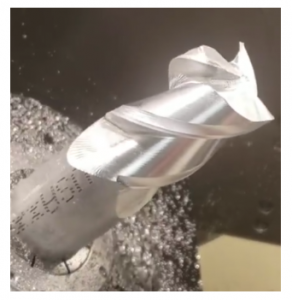 If you stopped by our booth at IMTS this year, you would have seen the Pocket NC tabletop Mill running a sample 5 axis job. Each year, 5 axis technology gains popularity as lead times get shorter, part batches get smaller and machines/software become more accessible.
It doesn’t matter if you are ready for it or not, 5 axis is likely to be a reality in your shop sooner than later. Let’s take a look at some of the features we used to set up and program this sample endmill using the BobCAD-CAM V31 5 Axis Mill Professional CAM software.
Machine Setup
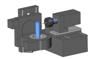
When setting up and programming any job, you’ll need to know where the machine setup location will be and how it’s aligned with the part. Even though we are programming a 5 axis job, this workflow is the same for either a 2D or 3D job.
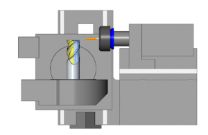
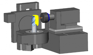
Pro Tip: Using machine simulation really helps visualize your setup and programming. All 5 axis BobCAD users have access to the machine simulation function.
3 + 2 Programming
When it comes to 5 axis part programming, you’ll want to remove as much material as you can using index systems. This is also known as 3+2 programming. Yes, you can program 5 axis roughing routines and for some applications that may be the right way to go, but for many, or should I say most, 3+2 programming is faster.
How does 3+2 programming work?
Have you ever programmed a job that needed multiple setups? 3+2 programming is very similar; the only difference is you don’t need to move the part from one setup to another, instead, the machine moves the part for you.
5 sided machining that uses the 3+2 method relies on index systems to align Z in the location where you want to machine.
In the following example, we will start by machining half way down on 1 side the part, then we will rotate the part 180 degrees and machine half way down on the other side.
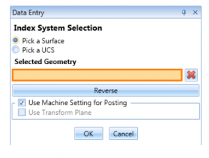
Creating an Index System
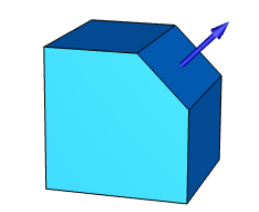
Setting up an index system in BobCAD’s CAM software is very easy to do. You’ll load and index system into the CAM tree and select either a surface or a UCS (user coordinate system). This selection defines the Z orientation of the machine to the part.
Once we’ve added the index system to our CAM tree, we can load machining features and start programming just like any 3 axis part.
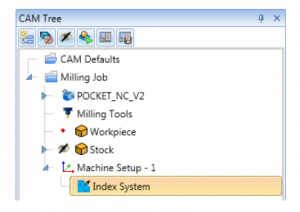
With the index system established in our CAM Tree, any of the toolpath features we create under that indexing system will be aligned to the UCS or surface picked to create the index system.
Subscribe to BobCAD-CAM's Tech Tuesday Blog
Join your fellow machinists. Get the latest Tech Tuesday CAD-CAM articles sent to your inbox. Enter your email below:
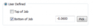
In our example, we are going to use an Advanced Rough toolpath to start removing material. To control how far in Z the toolpath is created, we’ll use the user-defined depth setting.
Since we are machining from a round stock, will the toolpath be cutting lots of air?
No, Advanced Rough is a stock aware toolpath, meaning it understands where the stock material is and the toolpath created trims to that stock.
After we’ve run the first Advanced Rough toolpath, we’ll want to create another index to rotate the part 180 degrees and machine from the other side. Using these 2 index systems, the roughing toolpath will remove the bulk of the material, but, did we get it all? It’s not always easy to tell if we did get it all, which is why we ran a deviation report to find out if there is any leftover material or gouges.
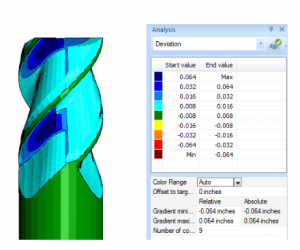
The report shows color mapping of the range of material left. In this example, we can see some darker blue areas showing us we still need a little more roughing before we can move to the finishing toolpaths.
To target the leftover material, we will create 2 additional index systems to gain access to the leftover material.
Pro Tip: You can copy and past machining features between index systems. This way you can use the same setting and tool as the first 2 index system without having to re-enter this information.
As we load and compute the Advanced Rough toolpath, we notice that the tool is re-cutting areas of the part where the material was already removed. How do we avoid this?
Operation stock is used to define the in-process stock and only target that material.
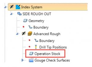
Users can select a solid model from the CAD screen or load an STL file from an external directory. Either method allows the user to select a model that represents where the material you want to target is.
Now that we’ve selected the operation stock, we’ll recalculate our toolpath. You’ll now notice how the toolpath only targets the leftover material.
How do you use the simulated stock as your operation stock?
The short answer is you save your cut stock as an STL and then select it as your operation stock. Simulation offers many different tools to evaluate your toolpath and machined stock. One tool you can use is the custom option.
CutSim is where you set the accuracy of the stock model, create section views and more.
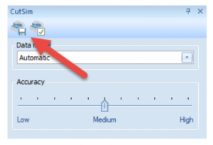
We’ll want to save our cut stock model which means we’ll click on the disk icon, saving our stock. Make sure you enter a name for your stock, save in a directory that you’ll remember and adjust the resolution of the STL as needed.
Now that we’ve saved our in-process stock as an STL, we can use that STL as our operation stock when needed. This is the workflow for saving simulated stock as an STL. At this point in our project, we’ve roughed and rest-roughed our part. Now, we are ready to start the finish machining.
That concludes part 1 of our 2 part series. Sign up for the newsletter and join us for part 2 as we go over Rest Machining! Thank you for reading another Tech Tuesday; see you next week!
Start your Test Drive.
Have questions? Call us at 877-838-1275.
You’re one click away from subscribing to BobCAD’s YouTube channel. Click the link below for tips, how-tos and much more!
To see if BobCAD’s Mill Turn software is right for your shop,