Questions? Call Us to speak with a CAD CAM Pro!
Are you getting stuck on the geometry setup for 2-axis lathe programming? In this downloadable help file example all the CAD preparation is done for you, the geometry is in the correct location and ready for selection. Wouldn’t it be nice if that was always the case, geometry you get from your customer may or may not be in the correct position for programming, it is very likely you’ll need to move your geometry into position among other steps to “prep the file” for creating toolpath. In today’s quick tip we will look at common design steps you could take to setup your geometry for 2-Axis lathe programming. If you are working with a solid for turning, this CAD CAM tip is for you!
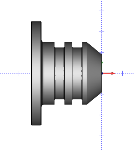
Geometry Orientation & Supported Format
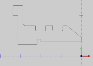
Before you can start creating a toolpath you’ll need to setup the part geometry like shown in the first image. Aligned with the world coordinate system, having your turned profile ( OD an ID ) on center and in the Y+ X-coordinate system. Your post-processor settings will adjust radius or diameter mode, XZ output, and canned cycles. Limiting where you cut, cutting direction and tool orientation is a combination of your selection and feature type, and wizard settings. Right now we want to focus on how to move the model into position and what cad tools to use to create the necessary wireframe geometry from the model for turning.
*This is a BobCAD CAM Stand alone step, if you run BobCAM for SOLIDWORKS there are additional selection tools to work directly with the model eliminating the need to create wire frame.
Align Geometry for 2-Axis Lathe
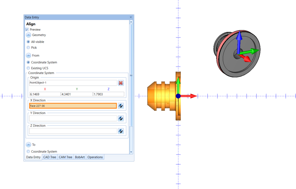
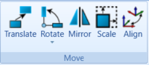
First introduced in V33 the align function combines translation and rotation, which saves time by simplifying the positioning workflow of geometry for 2-axis lathe programming. Imported parts often require repositioning due to differences in coordinate systems or in assembly position export. Using the Align CAD feature ensures accurate positioning with less effort on imported geometry.
Geometry Positioning for 2 Axis Lathe
In many cases, positioning geometry involves both translating (moving) it along a linear axis and rotating it around an axis to achieve the desired orientation. Performing these operations separately can be time-consuming, especially when working with complex models. However, the align function combines both translation and rotation into a single operation, allowing users to achieve the desired position and orientation efficiently. This streamlined approach significantly saves time by eliminating the need to perform separate translation and rotation steps.
Wireframe Geometry for 2 Axis Lathe
What methods in BobCAD can you use to create wireframe geometry for lathe programming? The choice of method depends on the model and the specific geometry required for the job.
Extract Edges:
Extracting edges involves selecting the desired edges of a surface or solid model to create wireframe geometry. This method is commonly used as it allows you to quickly capture the essential features of a model without unnecessary complexity. It is particularly useful when creating reference geometry to find the center of, edge of and more.
Section View:
The section view method involves defining a cutting plane through a solid or surface model and extracting the wireframe geometry that represents the intersection between the cutting plane and the model. This technique is useful for creating cross-sectional profiles or obtaining specific views of the model for lathe programming.
Intersection Curves:
Intersection curves are created by defining the intersection between two or more surfaces or solids. This method allows you to extract wireframe geometry where different surfaces or solids intersect. It is helpful when working with complex models that require precise geometry representation for lathe programming.
Silhouette:
The silhouette method involves capturing the outermost boundary curves or edges of a surface or solid model. By extracting the silhouette, you can obtain the wireframe representation of the model’s external shape. This technique is often used to create wireframe profiles for lathe programming.
Spun Profile:
The spun profile method allows you to generate a wireframe representation of a profile by revolving it around an axis. This technique is frequently used for lathe programming, where you need to create rotational geometry, such as circular profiles, rings, or flanges.
Extract Iso Curves:
Iso curves are curves that maintain a constant parameter value on a surface or solid model. The extract iso curves method involves selecting specific parameter values and extracting the corresponding wireframe curves from the model. This method is beneficial when you need to create wireframe geometry based on specific parameters, such as constant diameter sections or evenly spaced curves.
Is it worth acquiring CAD/CAM for lathe programming?
Most CNC shops have a lathe, however, not all have CAD CAM for lathe. The difference is astronomical comparing the number of shops that use CAD CAM for Mills vs the number of shops that use CAD CAM for lathes. Milling and machining centers represent more than 80% of CAD CAM users, while for many 2-axis lathes less than 20% are programming with CAD CAM software. So, the question is, why aren’t you using CAD-CAM for lathe? Keep reading to learn the upside or CAD CAM for lathes and why you should program your lathe with CAD CAM.

Many resources are available for learning more about programming a 2 Axis CNC lathe. These include online tutorials, user forums, one-on-one, and professional training seminars.
Free Weekly Training Click Here | 1 PM EDT
Over the last 3 years, over 200 new features were added to our CAD CAM software.
Join our weekly training to learn what’s New with BobCAD-CAM, BobCAM for SOLIDWORKS, and BobCAM for RHINO.
Are your machines and projects getting more complicated?
Call Us to speak with a CAD CAM Pro!