Tech Tuesday is a weekly blog that addresses some of the most common questions and concerns that I hear throughout the previous week from users of BobCAD’s CNC software. Both customers and future customers are more than welcome to leave a comment on what they would like to see covered for the following Tech Tuesday.
Questions? Call Us to speak with a CAD CAM Pro!
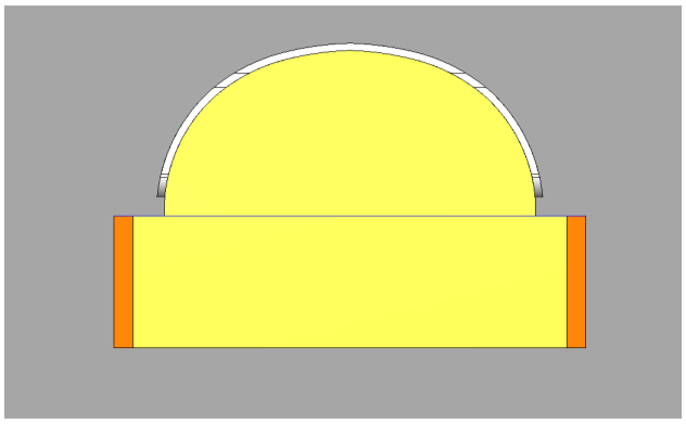
In this example, we can see a part above a fixture where the radius is not continuous around the geometry. We would not be able to use a wrapping group since the tool will have to follow around the rotary axis in more of an ellipse shape, continually changing the tilt angle around the rotary axis. We will need to use one of the surface-based toolpaths like Project Curves, which is included in the 4X Mill Pro package.
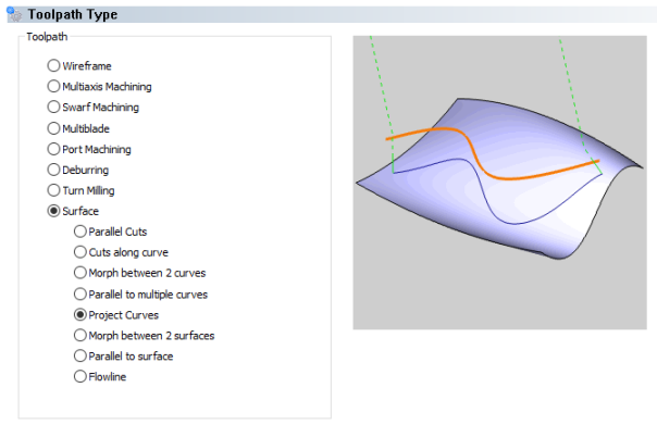
The Project Curves feature is used to create projected toolpaths using either a user-defined geometry curve, offsets of that curve, a radial pattern, or a spiral pattern. When selecting curve geometry directly from a surface, the projected toolpath is identical to the original. When the curve geometry is above the surface there are multiple possible results depending on the scenario and parameter selections. This pattern can be used to create engravings as well as spiral or radial finishing patterns for complete surfaces. In this case, we will be creating a radial finishing pass around this part. To begin, we will right-click on Machine Setup – 1 in the CAM Tree of an existing milling job and select Mill Multiaxis. We then select the Project Curves operation type under the surface-based toolpath operations.
After selecting this operation, we can skip to the tool page to define the specific tool we are using. In this example, we selected a flat endmill that will follow along the sides of the part in gray and follow right above the top surface of the fixture in orange. After the tool page, the next page allows you to select the geometry to define the toolpath. The first selection, Projection Curves, will be the top edges of the part in gray. As a side note, the Projection Curves could be wireframe from a solid model. It can even be geometry that has not yet been projected to a curved surface. The Project Curves operation will project the toolpath to the surface automatically.
This brings us to the Drive Surface selection. This is the surface the toolpath will be projected to. A couple useful options below this geometry selection include:
- Drive Surfaces Offset – is used to leave stock remaining on the part or to mill past the drive surface selected.
- Cutting Side – defines the tool compensation setting for the feature as Center (none), Left, or Right. We selected Left to offset the toolpath to the outside of the part when cutting clockwise around the part. You would select Center when creating an engraving operation.
- Cutting Side Offset – adds an additional offset of the toolpath from the projection curves. This is only used with the Cutting Side parameter set to Left or Right.
We did not change any other settings in this operation, but you can change the cut tolerance on this page. You could also tab to other pages for Tool Axis control to set this operation to 3X, 4X, or 5X toolpath and set a specific rotary axis. Other tabs include Gouge Check to check surfaces from gouging within the toolpath; Link to set the lead-in, lead-out, and linking between different areas of the part; Roughing if you want to add some roughing passes before the operation; and Utility for maximum angle steps around the rotary axis and other miscellaneous settings.
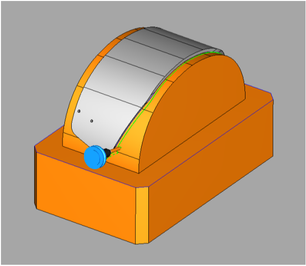
Here is the toolpath projected around the curved surfaces of the fixture. This functionality is available in the Mill 4X Pro package where the tool is able to rotate and move off of the centerline of the rotary axis.
Download a free demo version of BobCAD-CAM today!
Here are a few resources to use for all things BobCAD-CAM:
Our support site allows you to submit a ticket to technical support online:
www.bobcadsupport.com Our user forum is a community of other BobCAD-CAM users to share ideas and projects in BobCAD-CAM:
forum.bobcad.com
BobCAD-CAM has provided CAD-CAM CNC Software products to the global manufacturing industry for over 30 years. BobCAD-CAM software can be found to increase CNC productivity for many applications in aerospace, automotive, production manufacturing, mold making, general machining, woodworking as well as the medical manufacturing industry, consumer products, musical instruments, custom fabrication, defense industry and many others due to the products ability to automatically generate NC programming code for such a wide variety of CNC controllers. BobCAD-CAM software is also found in educational institutions throughout the world as well as independent hobby home use. Products include machining technology for 2, 3, 4 & 5 Axis CNC Milling, Routing, Waterjet, Plasma and Laser machines as well as 2 Axis CNC Lathe. BobCAD-CAM is modular allowing shops to start off at a reduced technology level and add technology as it is needed including an add-on, BobART, for artistic machining. Unique technology includes adaptive high-speed machining multiaxis milling and routing which is a first in the world of CAD-CAM software. BobCAD-CAM also provides a variety of quality training products that include regional and online training classes or private sessions tailored to specific applications. Professional certification and multi-tiered support solutions are available. Contact BobCAD-CAM directly for more information at 877-262-2231 or 727-442-3554
New Feature Spotlight – Tell us the topics that are most important to you Click Here
Questions? Call Us to speak with a CAD CAM Pro!