Tech Tuesday is a weekly blog that addresses some of the most common questions and concerns that I hear throughout the previous week from users of BobCAD’s CNC software. Both customers and future customers are more than welcome to leave a comment on what they would like to see covered for the following Tech Tuesday.
Questions? Call Us to speak with a CAD CAM Pro!
This topic explains the Allowances dialog, the options found in it, and will provide an example of selecting geometries to assign allowances to. The standard allowance options give you a global allowance option and a side and bottom allowance option as well. Then our new Advanced Allowance option offers an allowance for certain part geometry and for certain fixture geometry. We will take a look at how these options benefit programming your part by reducing air cutting and cycle times.
When setting up your Milling job, you must first define your workpiece. This is the desired part after you have machined it. Next is setting the stock. This is where the raw material is initially. Creating the initial stock helps BobCAM understand the necessary toolpath to machine down to the workpiece. After defining your machine zero in the Machine Setup page, you are ready to create a 3X roughing operation.
In this example, I created an Advanced Roughing operation, which is available in our Mill 3X Pro package. The operations in Mill 3X Pro include the allowance options that will further be described. After setting the tool and the specific cut pattern in the Advanced Roughing operation, the next page is the Parameters page. This is where you can set the depth of cut and stepover amounts. There are other options like setting a user-define top of job and bottom of job. This is where you can define The Z level you are starting at and the Z depth you want to finish at. That way, if there is any additional area that is already finished above or below these areas, there will be no air cutting at these levels. Next is to avoid additional air cutting on the sides of the part. Setting a boundary will trim the toolpath too far to not start the toolpath from the side of the stock. Using the part geometry option in the Advanced Allowances page allowed you to start from the side of the part and provide an optimized toolpath for your specific part.
Part Geometry
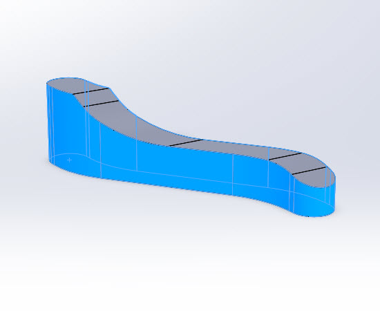
In the Part Geometry group, click Add. The dialog hides to allow you to select surfaces or solids from the graphics area. Select any geometry which will be assigned a particular allowance value that differs from the overall operation. All geometry selected here will share the same allowance value. Click OK. The Mill 3 Axis Wizard reappears. Click the Advanced button to launch the Allowances dialog again. Geometry 1 is now listed in the Geometry column. In the Type column, Global is used as the allowance type by default. To change to the Type, click the drop-down and select the desired option. Use the Global, Side, and/or Bottom allowance columns to assign a value to your selected geometry. Here are the selected surfaces to use for this part in the Advanced Allowance feature of part geometry.
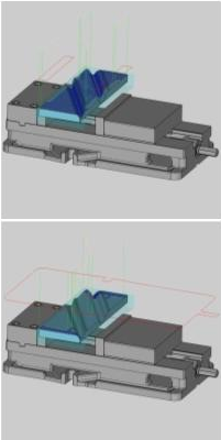
Selected Geometry
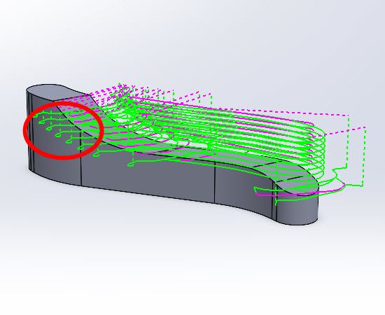
Resulting Toolpath
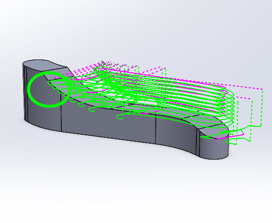
You can see that on the sides of the part, the toolpath is trimmed to optimize the way this part is being cut. We can now specify how close the tool should be away from the part before entering in from the sides.
Fixture Geometry
You can use the fixture geometry option also to avoid the fixture you are using when milling in 3D. This workflow eliminates the need to create a 2D boundary to contain the toolpath. V9 can support an assembly file for your fixture to be imported as.
In the Fixture Geometry group, click Add. The dialog hides to allow you to select surfaces or solids from the graphics area. Select any geometry which will be assigned a particular allowance value that differs from the overall Fixture Geometry. All geometry selected here will share the same allowance value. Click OK. The Mill 3 Axis Wizard reappears. Click the Advanced button to launch the Allowances dialog again. Fixture Geometry 1 is now listed in the Geometry column. In the Type column, Global is used as the allowance type by default. To change to the Type, click the drop-down and select the desired option. Use the Global, Side, and/or Bottom allowance columns to assign a value to your selected geometry. Here are the selected surfaces you can use in the Advanced Allowance feature of fixture geometry and the types of boundaries V9 creates for each geometry selection.
Selected Geometry
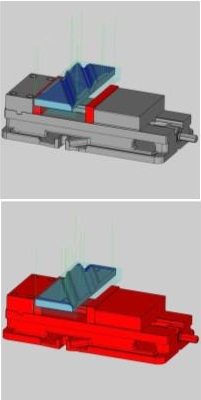
Resulting Silhouette
Try the new features found in BobCAM for Solidworks V9 Mill today!
BobCAD-CAM has provided CAD-CAM CNC Software products to the global manufacturing industry for over 30 years. BobCAD-CAM software can be found to increase CNC productivity for many applications in aerospace, automotive, production manufacturing, mold making, general machining, woodworking as well as the medical manufacturing industry, consumer products, musical instruments, custom fabrication, defense industry and many others due to the products ability to automatically generate NC programming code for such a wide variety of CNC controllers. BobCAD-CAM software is also found in educational institutions throughout the world as well as independent hobby home use. Products include machining technology for 2, 3, 4 & 5 Axis CNC Milling, Routing, Waterjet, Plasma and Laser machines as well as 2 Axis CNC Lathe. BobCAD-CAM is modular allowing shops to start off at a reduced technology level and add technology as it is needed including an add-on, BobART, for artistic machining. Unique technology includes adaptive high-speed machining multiaxis milling and routing which is a first in the world of CAD-CAM software. BobCAD-CAM also provides a variety of quality training products that include regional and online training classes or private sessions tailored to specific applications. Professional certification and multi-tiered support solutions are available. Contact BobCAD-CAM directly for more information at 877-262-2231 or 727-442-3554
New Feature Spotlight – Tell us the topics that are most important to you Click Here
Questions? Call Us to speak with a CAD CAM Pro!