Questions? Call Us to speak with a CAD CAM Pro!
Tech Tuesday is a weekly blog that addresses some of the most common questions and concerns that I hear throughout the previous week from users of BobCAD’s CNC software. Both customers and future customers are more than welcome to leave a comment on what they would like to see covered for the following Tech Tuesday.
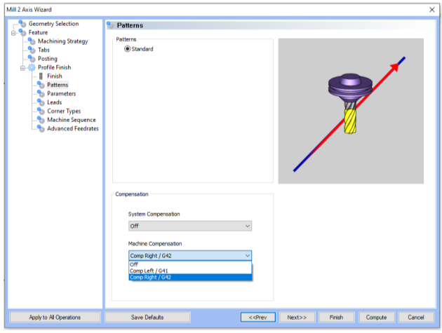
BobCAD-CAM is able to support different types of compensation for your milling tools in milling operations. Understanding our terminology for tool compensation types will help with your specific milling strategy. We will be focusing on a profile operation under the Mill 2 Axis Wizard. You can see there are two drop-down options for compensation, system and machine compensation.
In some cases, we may want the center of the tool to follow the path we select, but in most cases, the path we choose represents the final surface of our finished product which would be ruined if the center of the tool were to travel along it. This is where our compensation choices come in. With compensation we can specify whether the center of the tool should move along the selected path, or whether the tool should follow an offset path based on the radius of the tool. If the tool is to follow an offset path, should that path be offset to the left of the tool direction, or to the right? For every 2 Axis CAM operation in BobCAD-CAM we decide how to handle this with System Compensation, and Machine Compensation:
System Compensation:
The compensation is handled in the toolpath of the operation. The toolpath itself will be offset from the selected geometry, and the output code will follow this toolpath. With this option On, the system offsets the geometry by the tool radius. With this option Off, you should use Machine Compensation.
- Off – the toolpath is calculated from the center line.
- Left – the toolpath is calculated to the left of the selected contour.
- Right – the toolpath is calculated to the right of the selected contour.
Machine Compensation:
These options only affect the output in the posted code. The compensation is handled at the machine controller. BobCAD-CAM will output the codes for cutter compensation specified in the post, and the desired offset can be entered at the controller. The toolpath itself, and the coordinates of the output path, will not be affected by this compensation option.
- Off – the toolpath is calculated from the center line.
- Comp Left (G41) – the toolpath of the operation represents the center of the cutter. The post processed code includes the command for cutter compensation to the left of the contour.
- Comp Right (G42) – the toolpath of the operation represents the center of the cutter. The post processed code includes the command for cutter compensation to the right of the contour.
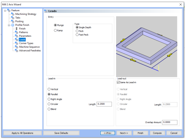
Note: For machine compensation, you will need to use any lead-in except for Vertical. This is because there is no X or Y location to offset for the tool radius. Go to the Leads page and change the lead-in from Vertical to a different lead-in.
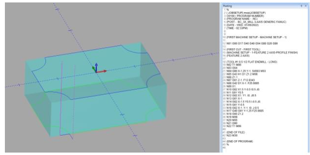
For the path shown below, we have system compensation turned off and machine compensation turned on. It is set to offset to the right of the path, outputting G42 in the posted code for the machine to offset the tool to the right of the profile path. The G41 and G42 codes being output at the machine allows users to set additional compensation settings at the machine, like tool wear compensation for example.
This information is also found in our Knowledgebase for common questions about various functions in BobCAD-CAM. Our Knowledgebase documentation can be found here:
www.bobcadsupport.com
Our user forum is a community of other BobCAD-CAM users to share ideas and projects in BobCAD-CAM:
forum.bobcad.com
Download a free demo version of BobCAD-CAM today!
BobCAD-CAM has provided CAD-CAM CNC Software products to the global manufacturing industry for over 30 years. BobCAD-CAM software can be found to increase CNC productivity for many applications in aerospace, automotive, production manufacturing, mold making, general machining, woodworking as well as the medical manufacturing industry, consumer products, musical instruments, custom fabrication, defense industry and many others due to the products ability to automatically generate NC programming code for such a wide variety of CNC controllers. BobCAD-CAM software is also found in educational institutions throughout the world as well as independent hobby home use. Products include machining technology for 2, 3, 4 & 5 Axis CNC Milling, Routing, Waterjet, Plasma and Laser machines as well as 2 Axis CNC Lathe. BobCAD-CAM is modular allowing shops to start off at a reduced technology level and add technology as it is needed including an add-on, BobART, for artistic machining. Unique technology includes adaptive high-speed machining multiaxis milling and routing which is a first in the world of CAD-CAM software. BobCAD-CAM also provides a variety of quality training products that include regional and online training classes or private sessions tailored to specific applications. Professional certification and multi-tiered support solutions are available. Contact BobCAD-CAM directly for more information at 877-262-2231 or 727-442-3554
New Feature Spotlight – Tell us the topics that are most important to you Click Here
Questions? Call Us to speak with a CAD CAM Pro!