Tech Tuesday is a weekly blog that addresses some of the most common questions and concerns that I hear throughout the previous week from users of BobCAD-CAM software. Both customers and noncustomers are more than welcome to leave a comment on what they would like to see covered for the following Tech Tuesday. Enjoy!
We partner with SOLIDWORKS to bring our customers some of the most powerful CAM systems on the market. BobCAM V6 Lathe for SOLIDWORKS gives you more power and performance for your CNC Lathe machines with this dynamic plug-in. For example, easily set advanced 2 Axis Toolpaths for OD & ID roughing, finishing, grooving, threading, boring, drilling and cutoffs. Let’s take a better look at all of the new Lathe features in our most easily understood CAM plug-in yet!
Spun Profile for Lathe Enhancement
Complicated or irregular shaped part geometry can be hard to nail down. They often require a lot of guesswork to develop machinable geometry for your CNC Lathe. BobCAM finds this geometry automatically for you when using our Spun Profile feature. Users simply select their model and our Spun Profile option does the rest, creating machinable geometry for the outermost and innermost dimensions of your part geometry. What a time saver!
Stock Tracking
Keeping track of where material is left can be a huge advantage in your process planning. It allows users to intelligently determine the best machining cycles to use, removing material fast and efficiently. BobCAM Stock Tracking keeps track of your in-process stock as you add turning cycles. Each Turning CAM features now has an operation stock item added to the Job Tree. BobCAM automatically populates the operation stock based on the previous operation, keeping track of the stock condition as you machine your parts.
Subscribe to BobCAD-CAM's Tech Tuesday Blog
Join your fellow machinists. Get the latest Tech Tuesday CAD-CAM articles sent to your inbox. Enter your email below:
Trim to Stock
Do you hate air cuts? Us too. Which is why you can use Operation Stock to eliminate unwanted air cuts. This feature was primarily developed for cast parts, allowing users to assign the cast profile as a boundary for turning cycles. Once the Operation Stock is defined, users can trim unwanted portions of Toolpath away with a sequence of boxes that you check, leaving BobCAM to focus on stock primarily. Goodbye air cuts! This upgrade is sure to keep your machine running at optimal performance.
New Lathe Tool and Holder Definitions
A complete overhaul of the Lathe tools. This includes ISO standard insert definition and easily made tool holders without the need to create the geometry manually. This puts a lot of time back in your pocket to spend another way.
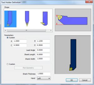
Users can choose from additional standard tool insert types like trigon inserts without needing to create custom geometry for these insert types.
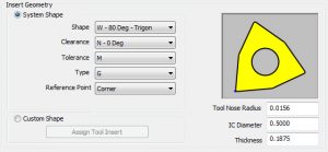
Another needed upgrade for BobCAM’s turning software was the addition of insert reference locations. Users now have more options when it comes to their tools reference location. Choose from corner, tip and center for roughing inserts.
Feature Type and Regions
BobCAM’s feature-based programming takes the guesswork out where your Toolpath is created and what direction the tool will be driven. Prior to BobCAM’s feature-type, users would use an orientation number to define the side of the part and the direction of cut their Toolpath cycle would produce. Users found this method to be difficult to understand and lacked the clarity needed in the fast-paced shop floor environment. BobCAM’s V6 feature-based programming makes it easy to determine the type of cycle by choosing from its feature types.
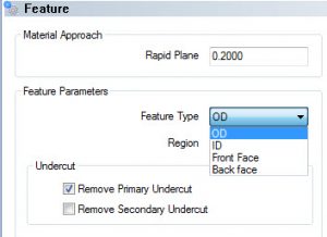
To control the direction of cut, BobCAM provides region types. Region 1 creates tool motion from left to right, Region 2 creates tool motion from right to left. This new workflow makes turning a profit that much easier.
Constraints
Another huge advancement in Lathe programming is the addition of Constraints. It gives the user the power to define the area that Toolpath will be generated with no need to trim and extend geometry. Users can choose from 3 types of toolpath constraints.
From Stock
-Sets the Top of Feature to the highest point of the stock diameter.
From Feature
-Sets the Top of Feature to the highest point of the selected feature geometry.
Custom
-Sets the Top of Feature from the highest point of the selected feature geometry to the value entered. You can also pick a point as well.
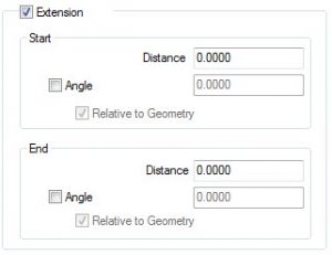
Extension
Having your tool start off the edge of your part or extend past the center line has never been easier. Using Extension, users can trim back or extend their Toolpath further along their selected feature geometry. In prior versions, this type of adjustment required the feature geometry itself to be directly edited. This is no longer the case with the new Extension feature, available to all turning cycles. Users can modify the Start and End location of their Toolpath by entering a positive value to extend and a negative value to trim. Extensions are done at the feature level and require no direct geometry edits.
Automatic Removal of Undercuts
Undercut geometry can slow down your workflow by driving the tool into unwanted cutting areas. In prior versions, the only method to avoid undercuts was to edit your feature geometry directly. New to the BobCAM V6 is the automatic removal of undercuts. Users can choose to remove undercut geometry that runs parallel to the Z and X Axis by using a checkbox. This streamlines your OD and ID part programming!
Grooving
BobCAM V6’s grooving options are expanding to handle the most common grooving needs. Users can choose from 3 groove patterns that include a standard groove, single-pass or zig zag groove cycle. BobCAM V6 now offers powerful grooving features that make it easy to program with current grooving tools and grooving scenarios. Like the single-pass groove, users can select their model geometry and choose from the center, beginning or end of the geometry to create a single-pass groove.
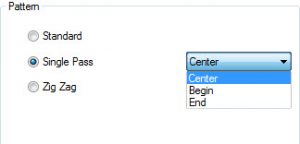
In the past, single pass grooving cycles only occurred with the geometry selected and the groove insert were the same size. With V6, you can select any groove geometry and choose to take a single pass and any of the 3 locations.
V6 is packed with industry-leading features, streamlining your design-to-code workflow, allowing you to program 2D and 3D parts inside SOLIDWORKS. There are many resources available to new V6 users to get them turning, including these Getting Started videos and the V6 Training Professor Series. Thanks for reading, tune in next week.
Start your Test Drive.
Have questions? Call us at 877-838-1275.
You’re one click away from subscribing to BobCAD’s YouTube channel. Click the link below for tips, how-tos and much more!
To see if BobCAD’s Mill Turn software is right for your shop,
Summary
Article Name
Tech Tuesday: Key New Lathe Features in BobCAM V6 for SOLIDWORKS™
Description
We partner with SOLIDWORKS to bring our customers some of the most powerful CAM systems on the market. BobCAM V6 Lathe for SOLIDWORKS gives you more power and performance for your CNC Lathe machines.
Author
Michael Downss
BobCAD-CAM