Tech Tuesday is a weekly blog that addresses some of the most common questions and concerns that I hear throughout the previous week from users of BobCAD-CAM software. Both customers and future customers are more than welcome to leave a comment on what they would like to see covered for the following Tech Tuesday. Enjoy!
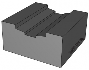
Have you ever been working on a 3D project and found yourself frustrated trying to control your toolpath? Either it’s cutting too deep or it’s not cutting deep enough, or maybe it’s on the edge of the part and you need it to go past the edge. Well, you wouldn’t be alone! Let’s take a look at the features BobCAD-CAM CNC software offers to help you control 3D toolpaths. We will start with the part model below.
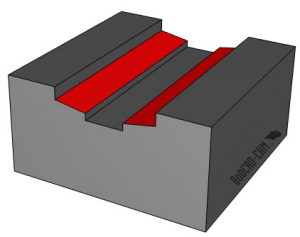
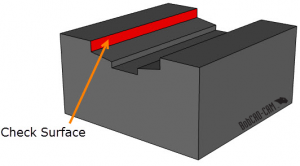
The surfaces we want to take a closer look at are the red surfaces shown here:
So, let’s back up for a minute and take a look at what toolpath we’ll use to remove the bulk of the material. In this example, we could use a Z level rough or advanced roughing toolpath which would do a great job removing the material quickly. But for now, we are going to use 2D adaptive pockets.
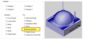
Now that we have run the pockets, we can focus on the shallow taper wall. In this example, we will be using the BobCAD-CAM Mill Professional Advanced Planar toolpath.
The plan is to run the toolpath down the length of the wall, starting from the inside pocket and working its way to the wall.
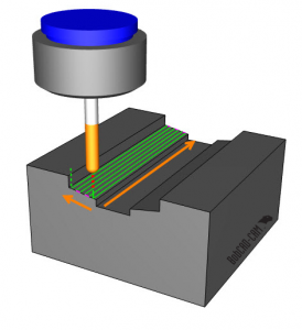
We’ll be using a zig-zag pattern with a lace angle of 180 degrees. We will also set the start corner to the upper right. Using these settings, the toolpath will start where we want it to and go in the proper direction.
Subscribe to BobCAD-CAM's Tech Tuesday Blog
Join your fellow machinists. Get the latest Tech Tuesday CAD-CAM articles sent to your inbox. Enter your email below:
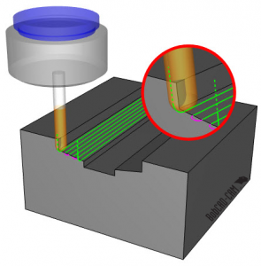
As you know, when we talk about 3D milling, typically it’s recommended to select the complete model. The reason being that the automatic gouge checking is based on the geometry you’ve selected. In this next example, we are going to do things a little different. To focus the toolpath on an angled wall, we will only select that surface.
Again, because the automatic gouge check is based solely on the surfaces selected, we instantly encounter a problem… the tool gouges the wall!
We’ve achieved the toolpath starting where we wanted and it’s cutting in the direction we need it to. Now, how do we keep the tool from running into the wall? As you know, the toolpath is based on the selected geometry, so couldn’t we edit the geometry itself to fix this issue? Yes, we could, but there is a faster and easier way to remove the unwanted toolpath.
As we’ve talked about in the past, a popular option would be to use a boundary. We can create a 2D wire boundary that keeps the tool away from the wall.
Using a boundary will contain your toolpath in X & Y and with this example, it works. It does require you to create the wire frame boundary. Not the worst approach, but there are faster ways.
What if we could select the wall surface and just tell the software to stay away from it? Well, the good news is, that’s how gouge check with check surfaces works.
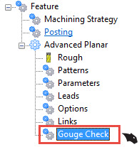
Select the surface(s) you way the software to look at and if the tool comes within an allowance, you can choose to trim the toolpath away or have the tool retract.
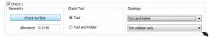
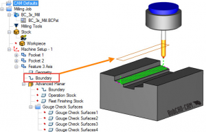
With this example, we want to select the wall surface as our check surface and we’ll use Trim and Relink as our strategy.
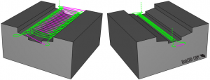
Now that we have our check surface selected and we picked our strategy, all we have left to do is recompute the toolpath.

You can see in this before and after image that by using the check surface option, we were able to eliminate the tool from running into the wall. This is a good example of how you can use check surfaces and gouge checking to aid in your 3D part programming. Thanks again for reading another Tech Tuesday; see you next week!
Start your Test Drive.
Have questions? Call us at 877-838-1275.
You’re one click away from subscribing to BobCAD’s YouTube channel. Click the link below for tips, how-tos and much more!
To see if BobCAD’s Mill Turn software is right for your shop,
Summary
Article Name
Tech Tuesday: Using Check Surfaces in Your CNC Software To Control Toolpath
Description
Have you ever been working on a 3D project and found yourself frustrated trying to control your toolpath? Either it’s cutting too deep or it’s not cutting deep enough, or maybe it’s on the edge of the part and you need it to go past the edge. Well, you wouldn’t be alone! Let’s take a look at the features BobCAD-CAM CNC software offers to help you control 3D toolpaths. We will use the image below as our part model.
Author
Michael A. Downss
BobCAD-CAM Software