Get answers to all the important questions about making your parts stand out using patterns and textures.
Subscribe to BobCAD-CAM's CNC Software Blog
Join your fellow manufacturers! Get BobCAD-CAM’s latest CAD-CAM articles straight to your inbox. Enter your email below:
1) What program are you using to create your sample parts, BobCAD-CAM or SOLIDWORKS™?
The sample parts used in these webinars are a combination of files drawn in SOLIDWORKS and files drawn in BobCAD-CAM.

2) What is different about your stepover – comparing 2D pockets and 3D toolpaths?
The concept of stepover is the same for both 2D pockets and 3D surfacing. The potential difference is related to the curvature of the geometry that you’re machining in 3D, and the effect it has on your toolpath.
In 2D pocketing, the curvature is the same. It’s “flat” – so your stepover consideration is only for looking at how much the tool is engaging in the XY plane.
In 3D milling, curvature changes can have a big impact on the tool engagement. As the curvature changes – so does the area of the surface.
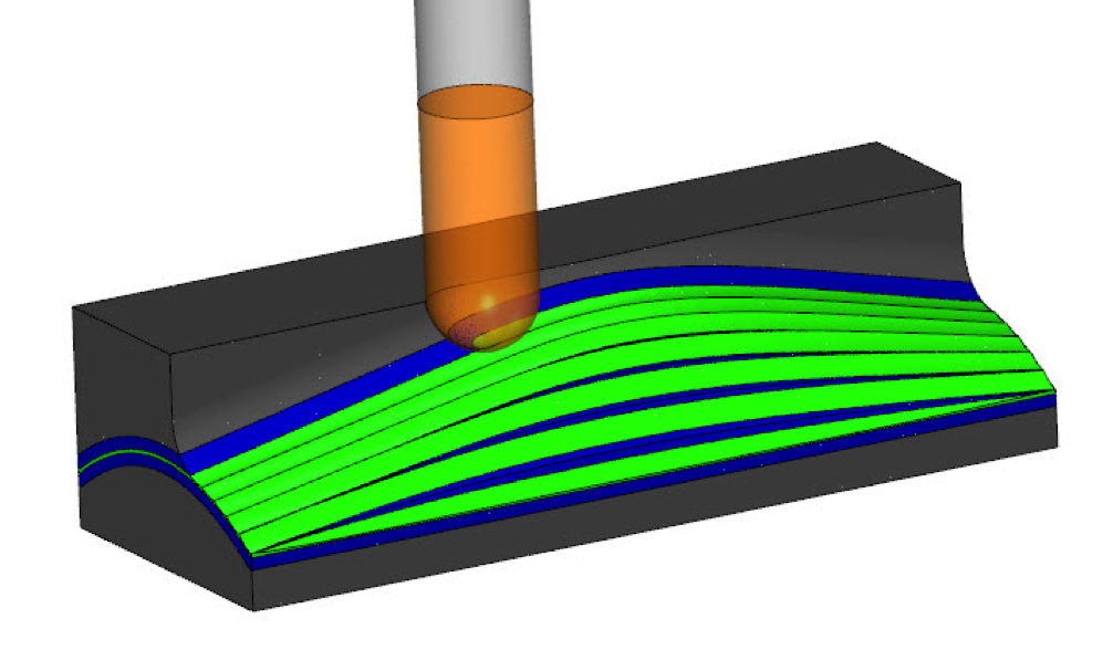
If you’re using the equidistant toolpath, the stepover is based on the area of the surface. This is in contrast to an incremental stepover in X and Y, which doesn’t account for the area or curvature of the surface. Planar toolpath would be an example of one that uses an incremental stepover in X and Y.
3) Why do people choose plunge roughing as a roughing routine?
There are multiple benefits of using plunge roughing for material removal, including:
– Low spindle RPMs are needed
– Tool pressure is on the Z axis
Depending on the machine you’re running, plunge roughing may be the best choice for higher removal rates.
4) Does plunge roughing output as a drill cycle or Z moves?
They are posted in line moves.
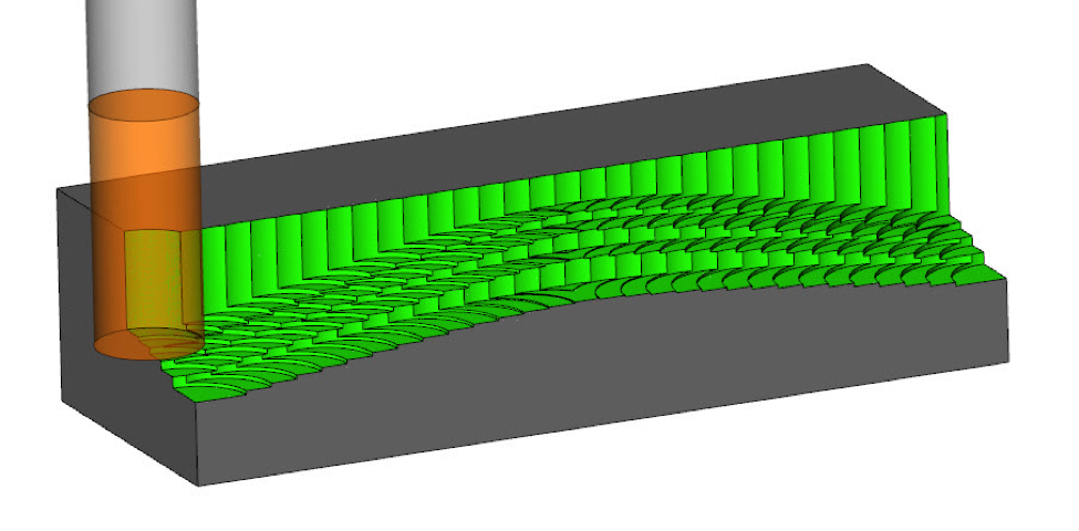
5) What patterns does plunge roughing offer?
Users can choose a zig or zig zag pattern and a defined lace angle. They can also define the stepover in 2 directions.
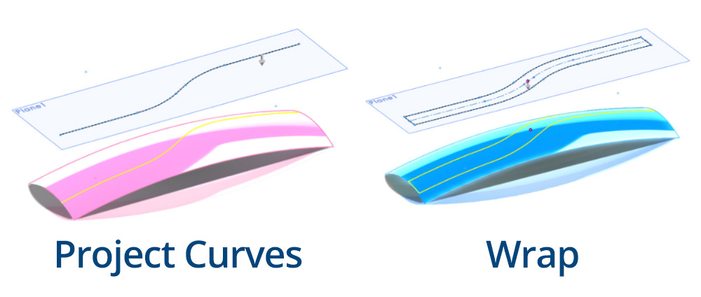
6) Can you project a sketch on a surface in SOLIDWORKS?
Yes. You can, using a wrap feature or projected curves.
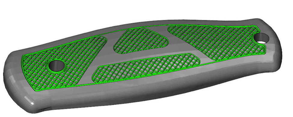
7) Can you create raised logos and letters using 3 axis wireframe?
Yes. Using 3 axis wireframe or project curves, you can create a toolpath layout that would result in raised letters or a raised logo.
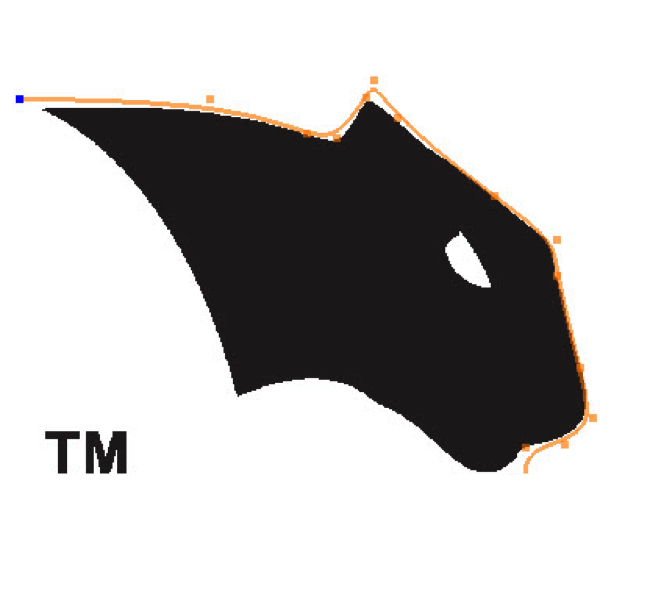
8) Can you trace in BobCAD-CAM to convert images into lines and arcs?
Yes. Using BobART, you can load images in the background and trace over them or vectorize them.
9) If I wanted to take multiple passes to rough out a pattern, what are my options?
The Mill Standard toolpaths offer a stepdown option. When using the Mill Pro toolpaths, you’ll use toolpath patterns to “step” the toolpath down.
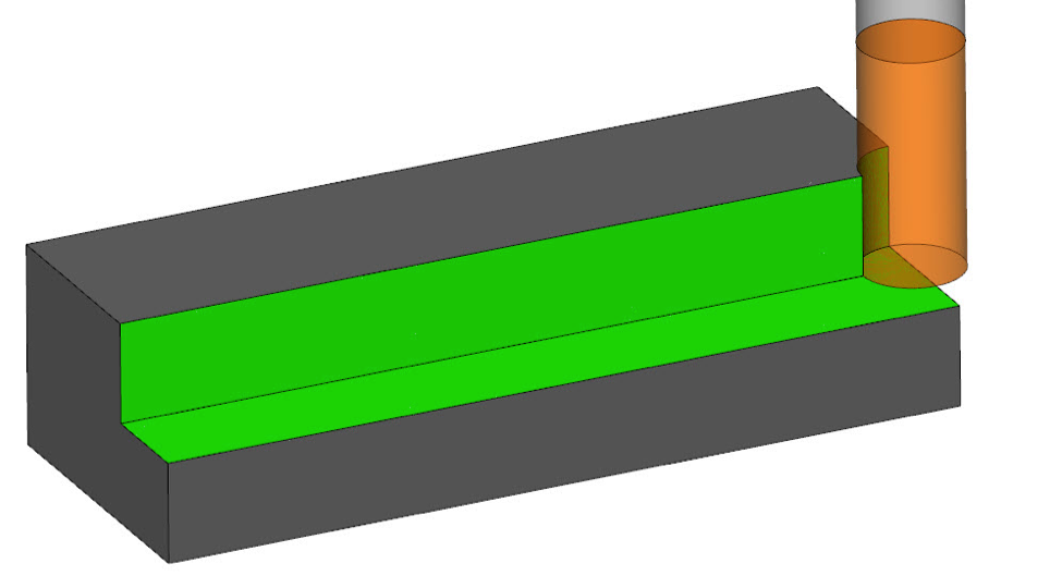
10) Can you get rid of the link moves on your surface when using zig zag?
If you’re a Mill Pro users, you can use the max link gap filters to produce a direct link move on your surface to force the tool to clearance to reposition.
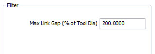
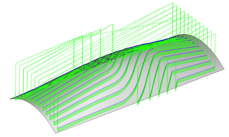
11) What is the max link gap filter and how does it affect links with the planar toolpath?
The max link gap is used to determine if the toolpath does a direct link on the surface or if the tool goes to clearance to reposition for the next cut. The gap value is a percentage of your tool. The default is 200% and works in most cases. If you want to reduce or eliminate the “direct link”, you can decrease the percentage amount.