At BobCAD CAM, we strive to keep all our modules current. Although our focus in recent years has been on machining toolpaths and cutting processes, some secondary modules like BobART still need significant changes. However, in BobCAD-CAM V35, a complete reconstruction of the art system was carried out, starting with its interface and workflow. This blog will explore the changes made to this module and how they help us reduce design and development time in processes such as photo positioning, vectorization, and reliefs.
Positioning
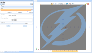
One of our most important goals is to eliminate the use of external programs to complete any project within our system. Previously, when a user wanted to use the art module to perform a vectorization process, they couldn’t modify the size and position of the photograph in the design area. For this reason, users of the art module had to use an external system like Paint or Photoshop to make these changes and then import the picture back into BobCAD-CAM to perform the vectorization process. Although it seems relatively simple, using another program is very tedious because if we don’t achieve the expected result in our vectorization, the user must return to the external program to modify the photo, save the changes, and return to BobCAD-CAM. This process must be repeated until the desired result is achieved.
Now, the system allows modifying the photograph’s size, position, and transparency within the BobCAD-CAM design screen. The importance of modifying transparency should be considered, as increasing the clarity of the picture allows us to review the vectorization result in more detail.
Vectorization
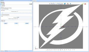
The most important function of the Art module is the ability to generate vectors from any photograph or image, regardless of its format or origin. As we know, the difference between pixels and vectors is that vectors can be cut in CNC, and the cleaner they are, the better the cutting result will be.
Although BobART has always allowed for clean vectorization, achieving a good result is tedious because vectorization is performed separately from the CAD screen. Therefore, the user must define the grayscale levels and precision in the vectorization screen to see the result on the CAD screen. Then, they must check if they are satisfied with the result and return to the vectorization screen to modify the details they want to improve or change. This process is repeated several times until the result is satisfactory.
For this reason, we have completely redesigned the user interface of BobART. Now, the user performs the vectorization process directly on the CAD screen. Thanks to this, every time the user modifies parameters such as pixel precision, grayscale levels, or segment size, they can see these modifications in real time, allowing for more accurate and faster changes.
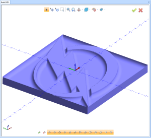
Relief
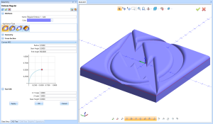
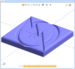
The relief processes are other functions that benefit from the new user interface. Just like in the vectorization process, users can see the result of the changes they make in real-time. For example, if the user modifies the relief height or direction, they can see the difference on the design screen. Additionally, we have implemented the ability to close the reliefs to generate complete solids. This allows for machining processes or 3D printing of fully enclosed pieces, as in previous versions, all relief processes were generated as hollow geometry, complicating printing or machining processes.
Real-time Relief Changes
Smoothing
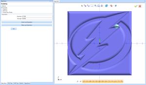
Negative and Positive Relief
Remember to sing up to our training event tomorrow July 12 at 1 PM Eastern Time
Click here the join us
Live Training Event