Tech Tuesday is a weekly blog that addresses some of the most common questions and concerns that I hear throughout the previous week from users of BobCAD-CAM software. Both customers and future customers are more than welcome to leave a comment on what they would like to see covered for the following Tech Tuesday. Enjoy!
Have you ever started to program a part and get stuck halfway through? It can be really frustrating and time-consuming, especially when you know in the back on your mind that there is a simple solution to get you back on track. Let’s take a look at programming an undercut using a T cutter and its workflow. Welcome to another Tech Tuesday, let’s get started.
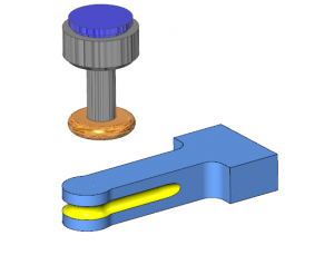
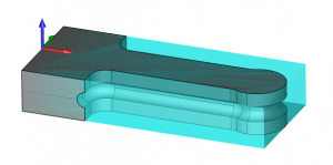
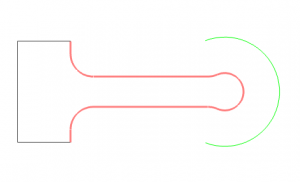
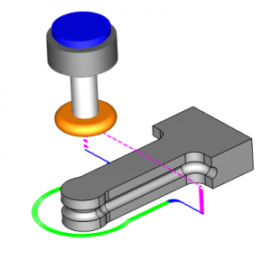
This is the result we are after, using a T cutter to create an undercut profile for a forming die.
To get started, anytime you open a new file in your CAD-CAM software, you’ll likely want to pull some dimensions off the model. This way you can verify what tooling information you may need to aid in the programming.
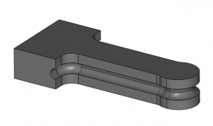
This is the part model that we are starting with. So, how do we create dimensions for the radius size and location of the undercut?
When creating geometry in BobCAD, it begins with the active UCS (User Coordinate System). By default, BobCAD’s active UCS is the top plane. In our example, we want to pull some dimensions off the side profile of the part. In order to create these dimensions, we’ll need to create a UCS on the side of the part. This is a very easy process with many options to choose from.
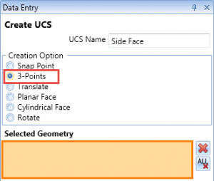
In our example, I am using a 3 point method to create the UCS for the side profile of the part.
Subscribe to BobCAD-CAM's Tech Tuesday Blog
Join your fellow machinists. Get the latest Tech Tuesday CAD-CAM articles sent to your inbox. Enter your email below:
Using the 3 point method, we are able to select 3 points from the model to create our new UCS.
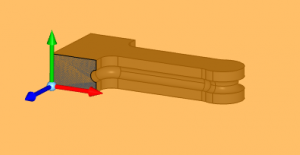
As you can see in this image, we’ve created a UCS for the side face of this model. Our next step is to create some wire geometry for this face. Yes, we can pull dimensions right off the solid model, but when working with wireframe, you’ll have more snap points to choose from.
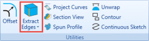
Using the create 2D tab and extract edges, we can select the face of the model and convert it to wireframe.
The resulted geometry for the side face looks like this:

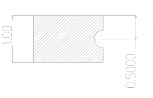
Now that we have our wireframe geometry, we’ll use the new auto dimension tool to create the necessary measurements.
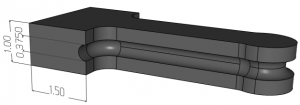
Now that we have some basic dimensions and understand the thickness of the part, the size of the undercut radius and its location in Z, we are ready for the next step.
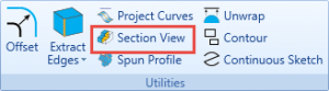
Our next step is to create a wireframe profile that we want to drive our cutter towards. Yes, we can drive our 2D toolpath directly off the model, but in our example, we do not have a profile chain for the leading edge of our undercut profile. So, let’s create one, using the create 2D tab section view we can intersect our model with a section plan and create wireframe based on that intersection.
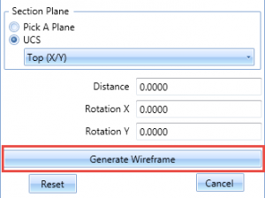
We can choose what plane we want the section view to be based on or even pull the section plane up or down, or along an angle for custom results. In our example, we will use the top UCS as our section plane.
Using the section view on our customer supplied part, we run into a problem. The section view didn’t come up pink.
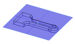
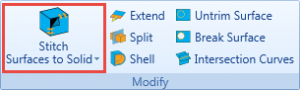
Why does this matter? When using section view, the section needs to show up pink in order to create wireframe from the section. If it doesn’t turn pink, there is a geometry problem. In our example, the problem we are working with is a surface model, not a solid model. So, we’ll need to stitch our surface to a solid before we’ll get our section view wireframe profile.
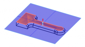
Once our surfaces are stitched together as a solid, our section view will turn pink.
We’ll use the generate wireframe option from our section view to create the profile we are after.
At this point in our example, we have the measurements of the model and a wireframe profile to drive our T cutter.
We’ll create a new job, set up our stock and load a 2 axis machining feature.
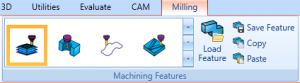
In our example, we will choose a profile rough feature.
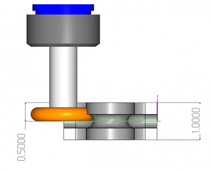
Setting the proper depth for our T cutter. In our example, we want to drive our T cutter on our section view profile. We know the depth of the center of our undercut radius at .5. Would this be the depth value we would use to drive the T cutter?
No. The reason is because the zero location for our tool is at the bottom of the tool. If we drive our cutter to the .5 depth, the T cutter will be in the wrong position.
What we need to do is add the radius of our T cutter to the depth to align the T cutter with our undercut radius.
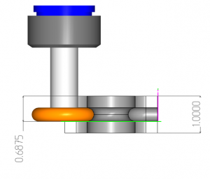
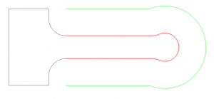
Now that we have the proper depth set, let’s take a look at the resulted toolpath.
As you can see in Green, the toolpath was only created on a section of the part.
Pro Tip:
If the resulted toolpath for a profile is not what you expected, it is typically 1 of 2 issue. One, the tool is too big to fit or, two, there is an issue with the geometry.
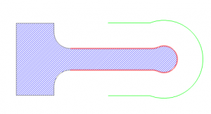
Why didn’t the toolpath follow our profile? In our example, it’s because the tool is too big.
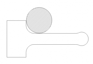
We are using a 1.75 diameter T cutter and as you can see in the illustration above, the tool doesn’t fit in the smaller corner radius profile of the part. When the software tries to offset for the cutter, the offset profile caves in on itself.
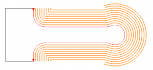
As you can see in this illustration above, as the offset gets larger, the offset folds in on itself until it trims away altogether.
Our option would be to choose a different tool size or edit the geometry. Because the inside radius is being used for clearance, we are going to change what our selection is to accommodate for the cut.
By removing the selection of the inside radius and line, you’ll see how the toolpath is created for or profile.
This creates an additional problem for us. Now the cutter is running into the side of the part so we need to adjust the profile to eliminate this. At this point, we could edit the geometry directly, but it’s faster and easier to use the toolpath trim/extend option.
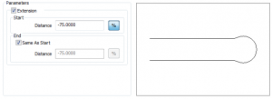
Using this option, we can extend or trim the profile based on a value or %. Use a positive number to extend and a negative number to trim.
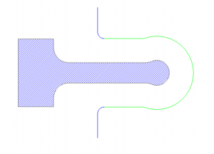
By trimming back our profile, the tool now has the clearance it needs. From here, we can add our lead-in/out so the tool starts off the part and ends off the part.
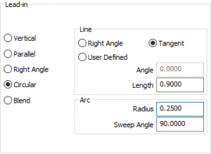
In our example, we will use a tangent circular lead-in/out and adjust the length to be greater than half our cutter diameter.
At this point, we have a working profile for our part. It’s set to the correct depth, it’s cutting where we want it too, everything looks good. But…. this cut is very aggressive. The tool will not be able to take the full radius cut in one pass. We need to take multiple passes in XY to work the tool into the part profile. So, how do we do that?
We will change from a standard profile to a side roughing profile pattern.
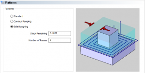
Using the side roughing pattern, we can tell the software how much stock we want to remove and in how many passes.
At this point, we’re done! We’ve created our 2 axis profile for our T cutter, cutting at the correct depth and side roughing the profile. That’s it for this week. Thank you for reading another Tech Tuesday; see you next week!
Start your Test Drive.
Have questions? Call us at 877-838-1275.
You’re one click away from subscribing to BobCAD’s YouTube channel. Click the link below for tips, how-tos and much more!
To see if BobCAD’s Mill Turn software is right for your shop,
Summary
Article Name
Tech Tuesday: Tips for Programming Your T Cutter in BobCAD’s CNC Software
Description
Here are some good tips and tricks for users that are programming a T cutter in BobCAD's CNC software.
Author
Michael A. Downss
BobCAD-CAM Software