Tech Tuesday is a weekly blog that addresses some of the most common questions and concerns that I hear throughout the previous week from users of BobCAD’s CNC software. Both customers and future customers are more than welcome to leave a comment on what they would like to see covered for the following Tech Tuesday. If you missed last week’s Tech Tuesday, click here.
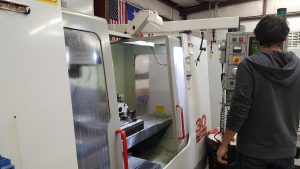 A CNC machine is controlled by a computer that is connected to motors and those motors drive to move the physical components of the machine function. The positions these components are moved in are defined using the Cartesian Coordinate System. The machines physical axes typically align with the X, Y and Z axis of the Cartesian Coordinate System. This allows the machine to move either the tool or the workpiece into a position in 3-dimensional space.
The instructions that tell the CNC controller what to move and how to move are defined in a text file called an NC or G-code program. The NC program will contain coordinates as to what, where and how the machine is to move so that the desired part is created using the tool and the material mounted in the machine. This Tech Tuesday will explain how the machine locates where to cut. When a CNC machine is powered up, it will commonly need to be sent to a home position.
This is a position on the machine where each axis will move to so that it can establish a known location (zero) for all components.
For a common Vertical Machining Center (Milling machine), this would have the machine move in the following way:
· Z-Axis – Up to max limit (this is the spindle axis. It moves up and down on a VMC)
· Y-Axis – Forward or back to max limit. Direction will be dependent on how the manufacturers set up the machine
· X-Axis – Left or right to max limit. Direction will be dependent on how the manufacturers set up the machine
For the remainder of this article, we will assume the machine will send the X and Y axes to the negative limit of the machine’s travel. The following image illustrates the total travel envelope the machine is able to operate in, as viewed from the top with the X & Y zero being set at the machine’s home position (bottom left corner).
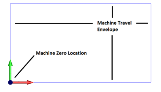
The red arrow indicates the X-axis positive direction (left/right with right being a positive direction move), and the green arrow indicates the Y-axis positive direction (forward and backward with a move going to the back as a positive move).
With the machine zero location established, we can now begin to think about the coordinates inside the NC program. The coordinate locations that are contained in the NC program. They also output in relation to a zero location that has been established in the CAM system for the part program. It is important to be mindful that the coordinates from the NC program fit within the travel limits of the machine.
Subscribe to BobCAD-CAM's Tech Tuesday Blog
Join your fellow machinists. Get the latest Tech Tuesday CAD-CAM articles sent to your inbox. Enter your email below:
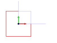
Let’s think through a simple example to illustrate this point. Below is a square part that measures 2 inches wide (X-Axis) by 2 inches high (Y-Axis). The zero of the coordinates for this part is directly in the center of the square (shown by the intersection of the red and green arrows).
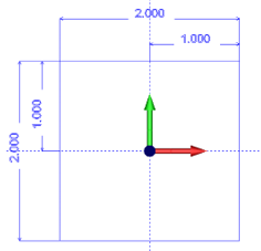 Here is a list of the XY coordinates for each corner of this square, starting from the 2 o’clock position and going counter-clockwise:
X1.0 Y1.0
Here is a list of the XY coordinates for each corner of this square, starting from the 2 o’clock position and going counter-clockwise:
X1.0 Y1.0
X-1.0 Y1.0
X-1.0 Y-1.0
X1.0 Y-1.0
If we loaded an
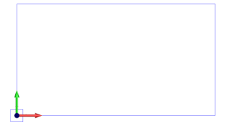
NC program onto the controller with the coordinates relative to the center of the part as shown, and we were running the machine where it’s zero location was set at a travel limit as previously described, the machine would not be able to cut the part. Why? Because much of the part would be outside the travel limit of the machine as shown below.
This image shows the overall travel of the machine with the square oriented around the machine’s zero location.
This image shows a zoomed in portion where the parts of the square in red are outside the travel of the machine.
 What are Work Offsets?
Work offsets are commands that allow the user to define different locations on the machine to be used as an XYZ zero location. Most machines have multiples of these work offset locations.
Fanuc is a common manufacturer of CNC controller and their standard work offset options are the following:
• G54 • G57
• G55 • G58
• G56 • G59
Each of these work offsets has a table of values the users can modify. This allows you to shift the XYZ locations from the machine zero to wherever you would like it in the machine travel.
Example:
G54 X:x.xxx Y:y.yyy Z:z.zzz
G55 X:x.xxx Y:y.yyy Z:z.zzz
G56 X:x.xxx Y:y.yyy Z:z.zzz
These work offset values are modified in the controller. However, there are special commands on some controllers that allow you to modify the value for each work offset’s value in the NC program itself. These values are usually adjusted from program to program based on the requirements of where the part needs to be located inside the machine’s travel.
Using the Work Offsets to Define New Program Zero Locations
In this section, we will use the work offsets (G54-G55) to define two new program zero locations inside the machine’s travel envelope.
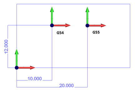
In the image above, we see the two desired work offset locations (G54, G55) & the corresponding dimensions of these locations in relation to the machine zero location. By entering these dimensions into the machine controller work offset tables, we can define these new zero locations on the machine. We can then use these new zero locations by calling up the desired work offset in the NC program.
Work Offset Table Values (In the CNC machine controller):
G54 X10.000 Y12.000
G55 X20.000 Y12.000
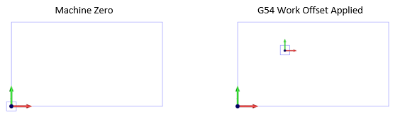
Let’s go back to our example rectangle we were looking at before. Below are two images showing the orientation of this rectangle. The left is where the program is located if run from the machine zero location and the right image is if the G54 work offset is set up and applied in the NC program.
That’s all we have for today’s topic on understanding work offsets in your CNC machine. Not all machines are made the same, so make sure to be mindful that the coordinates from the NC program fit within the travel limits of the machine and you should be just fine! Thank you again for reading another Tech Tuesday; see you next week!
Download the latest CAD-CAM software
You’re one click away from subscribing to BobCAD’s YouTube channel. Click the link below for tips, how-tos and much more!
BobCAD-CAM has provided CAD-CAM CNC Software products to the global manufacturing industry for over 30 years. BobCAD-CAM software can be found to increase CNC productivity for many applications in aerospace, automotive, production manufacturing, mold making, general machining, woodworking as well as the medical manufacturing industry, consumer products, musical instruments, custom fabrication, defense industry and many others due to the products ability to automatically generate NC programming code for such a wide variety of CNC controllers. BobCAD-CAM software is also found in educational institutions throughout the world as well as independent hobby home use. Products include machining technology for 2, 3, 4 & 5 Axis CNC Milling, Routing, Waterjet, Plasma and Laser machines as well as 2 Axis CNC Lathe. BobCAD-CAM is modular allowing shops to start off at a reduced technology level and add technology as it is needed including an add-on, BobART, for artistic machining. Unique technology includes adaptive high-speed machining multiaxis milling and routing which is a first in the world of CAD-CAM software. BobCAD-CAM also provides a variety of quality training products that include regional and online training classes or private sessions tailored to specific applications. Professional certification and multi-tiered support solutions are available. Contact BobCAD-CAM directly for more information at 877-262-2231 or 727-442-3554.