Tech Tuesday is a weekly blog that addresses some of the most common questions and concerns that I hear throughout the previous week from users of BobCAD-CAM software. Both customers and future customers are more than welcome to leave a comment on what they would like to see covered for the following Tech Tuesday. Enjoy!
Shorter cycle times are a huge motivation for many users of CAD-CAM. Saving time, running more projects and winning new customers are a top priority of any modern-day manufacture. So how does a toolpath editor help job shop manufactures reduce cycle times?
Let’s take a look at a simple drilling project and how using BobCAD’s V31 toolpath editor can reduce the cycle time on this project.
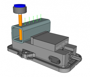
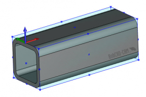
What we are looking to do is drill through holes in the square tube. To get started, we want to model the square tube, this way we can use it as our stock model.
“It’s always a good idea, when programming parts with a CAD-CAM system, to ‘setup’ your stock as close to the real thing as you can. This way, as you program your job, you’ll be able to visualize all the moving parts,“ says Al DePoalo, voice of BobCAD-CAM AfterDark.
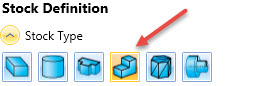
With the BobCAD-CAM V31 CAM software, users can choose from 6 types of stock, allowing users to accommodate for different initial stock conditions.
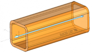
In our example, we will extrude our square tubing along the X axis.
Now that we have our stock model, our next step is to create a new job.
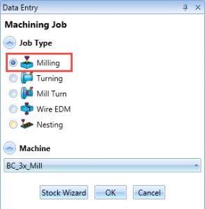
In our example, we are machining this project on a 3 axis mill, so our job type is Milling and our machine will be BobCAD’s BC_3X_Mill which is a generic vertical machining center.
Now that we’ve chosen the job type and the machine, we’ll click on the stock wizard to define our stock. BobCAD’s default stock type is rectangular which will put a ‘box’ around our part and tell us the minimum sized material we would need to program our job.
In our example, we want to use solid model stock, this way we can show the hollowness of our square tubing.
Subscribe to BobCAD-CAM's Tech Tuesday Blog
Join your fellow machinists. Get the latest Tech Tuesday CAD-CAM articles sent to your inbox. Enter your email below:
Now that we’ve selected our solid model stock, we’ll highlight the model and click calculate stock. As we advanced the stock wizard, our final step is to define our machine setup location/origin. This is your work offset location and it will need to match the work offset you define on the machine.
In our example, I am choosing the top left center location.
Ok, so far, so good. We’ve created our milling job and ran the stock wizard, defining our square tubing and our machine setup location.
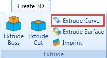
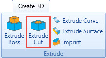
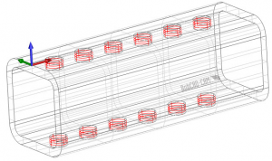
Our next step is to cut a hole in the model and program that hole to be drilled out. To create the hole in the model, we are going to use extrude cut.
We will select a group of arc locations and pull down to extend past the model edges. The result of the extrude cut command will be holes in our model on both sides.
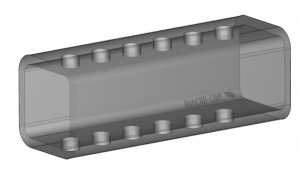
Pro Tip: To change the shading of your solid model on the fly, use the keyboard shortcuts ‘S’ for shading, ‘T’ for transparent and W’ for UV lines.
Now that we have our square tubing modeled with our hole locations, we are ready to create a drilling feature.
We can choose the drill icon from the Milling Tab of the ribbon bar.
Clicking on this icon will launch the Mill Hole wizard. BobCAD’s machining wizards are used to answer all the questions about the machining process in a step by step order. Users will also find graphic aids that make it easier to understand the options being presented.
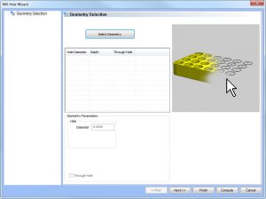
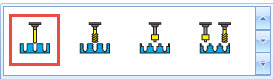
Our next step is to select the geometry that defines our hole locations. After clicking on select geometry, BobCAD’s hole geometry picking window will come up. Users can choose from Standard, Multiaxis or Cross Drilling types. In our example, we are going to use a standard drill type. The geometry we will select is the cylindrical faces of our hole locations.
To complete our selection, there are a number of workflows users can choose from: single picking on the cylindrical faces one at a time, a window selection from a top view or using a transparent view and selecting the UV lines of our hole surfaces. The user’s experience and the complexity of the geometry will determine which selection method is best for you.
In our example, using a transparent view & selecting the UV lines of our hole surfaces is the workflow I used.
Now that the hole geometry is selected, we will ‘OK’ the selection which returns us to the Mill Hole wizard. BobCAD will measure the hole diameter and the depth based on our selection.
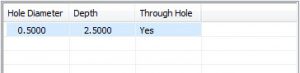
If we needed to make any changes to the hole size or depth, we can use the table to make an adjustment.
Our next step is to choose the machining strategy we want to use. BobCAD gives the user the ability to ‘process’ holes using multiple tools and cycles. In this example, we are going to drill our holes with a single tool and a single cycle.

Our next step is to choose our sort order & we will use the default option which is optimized.
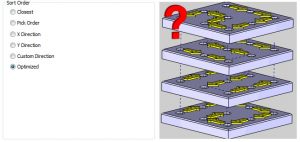
Sorting order is used to control the hole to hole order for your drill cycle.
Our next step is to pick our tool and set our speeds and feeds. By default, BobCAD will call a drill based on the hole size selected. You can modify the tool number as needed. As far as the speeds and feeds, BobCAD will use our material library to load the SFM and chip load. Users can override these values at any time or even setup tooling with specific speeds and feeds.
Speeds and feeds can vary by material, tooling, setup & machine. In our example, we are going to run the spindle at 1000 RPM and feed at 7 IPM.
Now that we have everything set up, we’ll compute our toolpath and take a look.
What we will find is all of our holes are drilled, so let’s take a look at the cycle time.
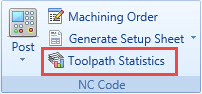
BobCAD’s V31 users have access to toolpath statistics, which provides detailed information about machining features in the CAM Tree. In our example, we will use this report to find out baseline cycle time that we’ll want to improve on.
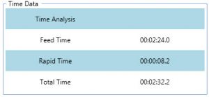
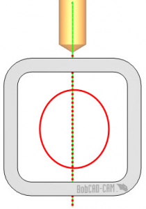
If we take a closer look at our part, we’ll see that our drill cycle is feeding through air as it passes through the void in our square tube. If we could increase our feedrate while the tool is in the void, we would reduce our cycle time.
Using BobCAD’s toolpath editor, we can make changes to the toolpath BobCAD creates. This is a very powerful tool to customize your toolpath, and in our case, reduce our cycle time.
What is the toolpath editor?
The toolpath editor is an editing tool that works directly on toolpath. When you calculate toolpath, the result is displayed in the CAD window. Users are unable to modify this toolpath anyway, unless they are using the toolpath editor.
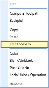
Users can access the toolpath editor by right-clicking on any operation and choosing it.
BobCAD’s toolpath editor offers 7 type of editing commands for directly editing your toolpath. In our example, we are going to use 2 of the editing commands.
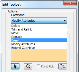
Break is used to create additional segments of selected toolpath.
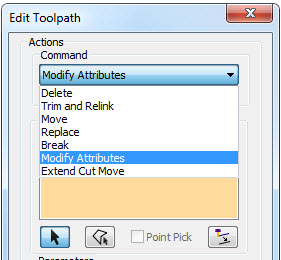
Modify attributes is used to change the feedrate type or value of selected toolpath.
If we increase our feedrate between these 2 sections, we will reduce our cycle time on this project.
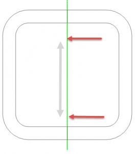
Using our toolpath editor, we will break our toolpath first hole and above the second.
This will give us a segment of toolpath that is in the void
Next, we’ll select that segment and modify its attributes increasing the feedrate.
In our example, we are drilling 6 holes that are evenly spaced. To speed up the editing process, we will only drill one hole, make our edits to the toolpath, then use a toolpath pattern to make copies. This workflow eliminates the need to edit the toolpath for each hole.
After making our changes, we can check out toolpath statistics for the updated cycle time.
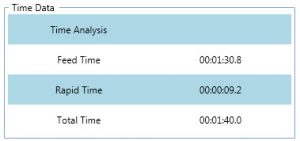
In our example, we reduced our cycle time from 2:32 to 1:40, reducing our time by almost 1 minute. Pretty wonderful, don’t you think? Thanks for reading another Tech Tuesday; see you next week.
Start your Test Drive.
Have questions? Call us at 877-838-1275.
You’re one click away from subscribing to BobCAD’s YouTube channel. Click the link below for tips, how-tos and much more!
To see if BobCAD’s Mill Turn software is right for your shop,
Summary
Article Name
Use BobCAD’s CNC Software Toolpath Editor to Reduce Cycle Times.
Description
Shorter cycle times are a huge motivation for many users of CAD-CAM. Saving time, running more projects and winning new customers are a top priority of any modern-day manufacture. So how does a toolpath editor help job shop manufactures reduce cycle times?
Let’s take a look at a simple drilling project and how using BobCAD’s V31 toolpath editor can reduce the cycle time on this project.
Author
Michael A. Downss
BobCAD-CAM Software