Tech Tuesday is a weekly blog that addresses some of the most common questions and concerns that I hear throughout the previous week from users of BobCAD-CAM software. Both customers and future customers are more than welcome to leave a comment on what they would like to see covered for the following Tech Tuesday. Enjoy!
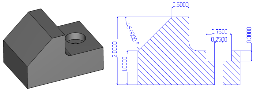
Pulling dimensions off your part models is an essential part of any manufacturing process. Let’s take a look at some of the features BobCAD’s CNC software offers to aid in the creation of part prints, inspection reports & measurements.
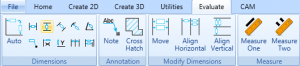
BobCAD’s measurement and dimension tools can be found under the evaluation tab.
Users can select surface edges, endpoints & wireframe geometry to create driven dimensions off of your part models. That’s correct, you can create measurements off your solid model directly without the need to create geometry. Will you need to create wireframe for some dimensions? Yes. Surface edges currently do not offer the same “snap” points as wireframe geometry does. So, let’s take a look at some of the ways to convert your solids into wireframe.
Subscribe to BobCAD-CAM's Tech Tuesday Blog
Join your fellow machinists. Get the latest Tech Tuesday CAD-CAM articles sent to your inbox. Enter your email below:
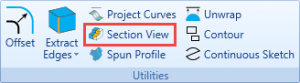
Under the Create 2D Tab, You see the Utilities section.
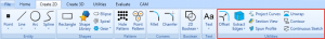
This is where you’ll find tools you can use to convert surfaces & solids to wireframe.

Use extract edges to convert surfaces to wireframe. Just select the surfaces you want wireframe for and click ok. BobCAD will convert your surfaces to wireframe.
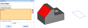
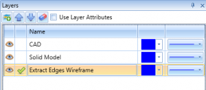
Pro Tip: Create a new layer and make it active prior to extracting edges. This will separate your solid/surface geometry from the newly created wireframe, making it easy to isolate geometry.
Another very useful tool for creating wireframe off your solids is section view.
Section view allows you to view a cross-section of your part. You can choose from the standard user coordinate system with the option to change its location or rotate to a custom angle.
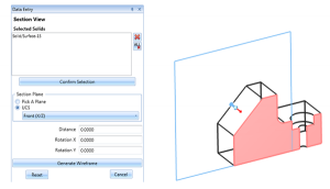
This feature is a great tool for “seeing” into your part, but you can also use this feature to create wireframe. Wherever the cross-section plane has intersected your model and the section comes up pink, you can use the generate wireframe option. This option will return a wireframe profile based on your cross-section.
Ok, now that we know of 2 methods of creating wireframe off our model, let’s take a look at measuring our model.
If you are trying to pull some measurement for the length of the part, the size of a radius or height values, using measure 1 or measure 2 is a great tool to start with.
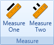
Measure One will provide detailed information about any surface edge, line, point, arc or spline that you select. For fast and easy measurement of a single entity, this is your go-to feature.
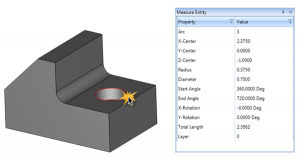
After you’ve selected a surface edge, line, point, arc or spline, the measure entity window will populate with detailed information about the entity you’ve selected.
If you are looking to measure the distance between 2 entities, that’s what Measure Two is used for.
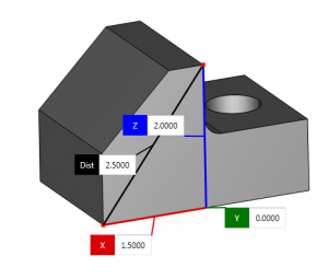
Select 2 endpoint locations and BobCAD will display measurement flags for the X, Y, Z and distance between those values.
Pro Tip: Sometimes you may need to move the measurement flags. Doing so is easy; just left click on one of the flags and the flag will drag with your mouse. You can also copy and paste these values using CTRL+ C for copy and CTRL+V for paste.
If you need more information about your model or sketches, this is when you’ll use the dimensions tools.
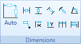
BobCAD provides you will all the tools you need to measure distances in X and Y angles, point locations, adding notes and more. Using dimensions auto allows you to access all of these dimension types with a single dimension feature.
Dimension auto works off of surface edges, point locations, lines, arcs & splines.
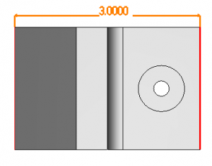
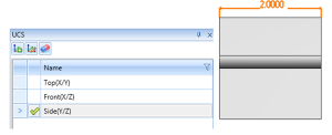
To create dimensions for different views of your part, make sure to change the active UCS (User Coordinate System) so it aligns with the view you want dimensions for.
Using a cross-section of your part, generate the wireframe and use the dimension tools to detail hidden features. It’s that simple! Thans for reading another Tech Tuesday; see you next week!
Start your Test Drive.
Have questions? Call us at 877-838-1275.
You’re one click away from subscribing to BobCAD’s YouTube channel. Click the link below for tips, how-tos and much more!
To see if BobCAD’s Mill Turn software is right for your shop,
Summary
Article Name
Tech Tuesday: Creating Dimensions with BobCAD’s CNC Software
Description
Let’s take a look at some of the features BobCAD's CNC software offers to aid in the creation of part prints, inspections reports & measurements.
Author
Michael A. Downss
BobCAD-CAM Software