CAD-CAM stands for Computer Aided Design and Computer Aided Manufacturing. This is CNC Software technology that allows us to innovate and design (CAD) and then to take those models and translate them into CNC (Computer Numerically Controlled) machining toolpaths and NC (Numeric Code) programs that get sent to a machine that makes it. These types of machines are milling machines, lathes or turning centers, routers, water-jet machines that use abrasive cutting methods and even lasers or burning machines. These do include CNC Plasma machines as well.
 A good example of this can be found in beverage container production manufacturing. The molds may differ in design while the general concept is still the creation of a beverage container. The general part models can be similar, yet one having more intricate detailing in the mold that requires the appropriate toolpath strategy such as Equidistant offset contouring and a REST finishing toolpath combination.
Subscribe to BobCAD-CAM's CNC Software Blog
Join your fellow manufacturers! Get BobCAD-CAM’s latest CAD-CAM articles straight to your inbox. Enter your email below:
 They are all types of computerized machinery that cut and shape various materials into that of the original CAD model. Basically, you have a machine that has a computer workstation built onto it that receives the program and drives the motors on each axis. This is called the “Controller”. The NC Code or “G-Code” that the CAD-CAM software allows the operator to create is then fed to the machine controller through what is called an RS 232 Communications cable. The operator can also save the g-code cam program onto a flash drive and take that to the machine controller. As controller continue to evolve, there are more options for a machine shop to send programs to their CNC machine tools. High tech shops are known to use remote DNC (Direct Numerical Control) products such as Predator DNC which can be installed wireless. Large wireless DNC networks can be created to relay NC programs from PC-Based CAM systems or DNC software products to their machines which can support the efficiency of a machine shop. Controller software can be provided by the OEM of the machine or acquired from popular and reliable providers such as Mach 3 or ArtSoft. A 3rd party controller software will actually turn a PC into a 5-6 Axis CNC Controller and provide all of the editing features and RS 232 communication features required to work well. Often times shops will have a manual machine in the shop that needs a retrofit. Companies such as MachMotion, Soutwestern Industries and Centroid CNC are all reliable sources and can certainly help with the process of performing a CNC Retrofit.
The Basic Stages:
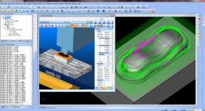
1. Innovation and design through the use of Computer Aided Design/CAD software.
2. The creation of CAM toolpath, CNC Machine Simulation and the G-Code / NC Program.
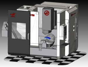
3. The program sent to the machine tool (Milling Machine as an example).
4. The actual machining of the part that was originally designed. This requires various materials, tooling, work-holding and more that is performed by the machine and a “CNC Programmer” or Machinist by profession.
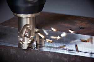
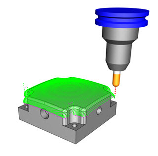 The word “Toolpath” is used to describe the path in which the machine cutter travels while cutting. There are typically 2 basic phases of toolpath called, Roughing and Finishing regardless of whether the toolpath is 2D or 3D in nature. This “roughing” toolpath allows a tool to remove the largest amount of material in the most efficient manner. Generally in multiple cutting levels from the top down to the determined bottom level of a part. CAM – Computer Aided Machining technology addresses what is necessary in roughing operations to generate clean and efficient cutting routes for a wide variety of CNC Milling and CNC Turning machine cutting tools. This HSM – High Speed Adaptive Roughing. High Speed Adaptive Roughing gives machinists a highly efficient style of milling where the machine can be run at higher speeds due to the circular cutting motions, among other variables, that the cutting tool uses during the machining process. High speed cutting toolpath is also known as Trochoidal Milling. The adaptive high speed roughing eliminates any right turns or left turns in a path that would result in a stop and go tool action.
This is all a result of CAM technology development over the last 20 years. Higher efficiency and CAM programming methods have continued to make CAD-CAM smarter, faster and easier to work with while extending cutting tool life and resulting in less wear and tear on machine tools over time.
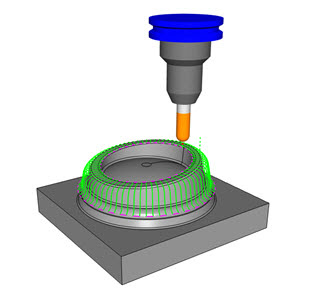 The next fundamental phase of the CNC machining process with CAD-CAM is called “Finishing”. The finishing toolpath allows the machinist to run a final strategy to clean up material that is left over from the roughing process and provide as close to a final result as possible. This is known as “Finishing”. Just as there are various machining strategies for roughing, there are also multiple strategies and toolpath styles used in finishing. These include, “Constant Scallop” or “Equidistant Offset Contour” or “Pencil Milling” as well as “REST” finishing where the toolpath cleans up the “Rest” of the material left over from semi-finishing. Finishing can be broken down into two aspects which are “Semi-Finishing” and then finishing. Semi-Finishing would include a Z-Level or Waterline strategy followed by the REST finishing to complete the process. This is because sometimes a finishing cycle can still leave extra material in hard to reach corners. Therefore a pencil or rest-finishing strategy will typically get all that is left.
CAD-CAM software provides important functionality such as Dynamic Machining Strategies™ which allows a CAM programmer to apply multiple toolpath operations to a particular roughing or finishing strategy that is connected to a CAD feature of a part model. The process starts by selecting a CAD feature, assigning multiple toolpath operations to the basic strategy and then automatically populating a “Wizard” with those operations so that the operator can edit them and create the toolpaths all at once. Machining Wizards remove programming guesswork and step an operator through a series of consecutive dialog pages to create toolpath which includes selecting tools from a library, setting up patters, the type of tool lead in and the type of lead out that the tool will take to be more efficient and avoid work-holding amongst other variables that are necessary in CAM. The idea is to make CNC programming streamlined and easy for the operator. The more intelligent a CAD-CAM software is, the better. Many machining strategies are made available in CAD-CAM as there are different machining situations. These can include Profile cutting, Pocketing, Engraving, Plunge cutting and advanced 3D milling. Not to mention all of the various hole-making processes, threading, boring and chamfer milling. CAD-CAM will streamline workflow by providing multi-tool drilling operations in one strategy. An example of this can be a Center Drill, Drill and a Chamfer in one operation or a Center Drill, Drill and Bore in one strategy. These are known as “Templates” or “Patterns”.
These are “End-Mill, Bull-Nose, Ball Cutters, Lollipop, Tapered End Mills, Face Mill Cutters, Form Tool Cutters and so many others. Each cutter has its own highlights such as what they are made of, how many flutes they have, whether they are tapered or not and much more. Different cutting tools are best used with different materials and under different circumstances. A good resource for learning more about machine cutting tools is sandvik.coromant.com.
 This is the CAD-CAM CNC machining process in its simplicity. Everything you see around you has been created in a manufacturing process that includes CAD-CAM technology. 35 years ago you would go to Sears for a coffee maker and only find 2 or 3 models available. Now in 2017 you will go to buy a coffee maker and you will see 20 different models, each looking modern and even aero-dynamic, one offering the latest in coffee-making features while all of them hosting competitive prices. This is directly associated to the growth and development in CAD, CAM and CNC manufacturing technology. From our Cell Phones and Automobiles and millions of consumer products to Sports Equipment, Jewelry, Space Shuttles and Mars Rovers, CAD-CAM and CNC Machining shapes the world around us. In recent years the Dental Industry has created special CAD-CAM software and machinery the creating dentures and implants. This alone has changed the way that the dental industry provides services to their customers as well as associated costs. The technology of manufacturing teeth, prosthetics and medical devices as all been affected by CAD-CAM and CNC automation. Because of this, Manufacturing Machine Shops can operate more efficiently, leaner and maintain a better profitability than possible 20 years ago. Small shops can compete with large manufacturing shops in their CNC work. Custom Fabricators can be more creative and achieve victories in complex part-making in a fraction of the time it took them 10 years ago. Jobs that were not possible are now not much of a challenge if the CNC shop has the right machine tools on the shop floor.
What can we all expect from CAD-CAM and CNC machining technology as we move forward? More of the same developments in the software will most likely include achievements in Computer Aided Engineering. The part-making process will become even more seamless than it is now. While the CAM “Cut My Part” button is still a ways away, the transparency between CAD design and CAM machine programming will continue to become smarter and more automated. More transparency between the CAD and CAM process regardless of the parts complexity be it 3, 4 or 5 Axis in nature.
There will be less setup between the designed model and the feature based CAM setup. Much of this has already taken place as CAM vendors have already developed into CNC machine multitasking and live Mill-Turn. Soon we will start seeing this become easier to use and for more competitive prices to shops that need it to gain or maintain their competitive edges.
BobCAD-CAM has provided CAD-CAM CNC Software products to the global manufacturing industry for over 35 years. BobCAD-CAM software can be found to increase CNC productivity for many applications including educational and independent hobby home use. Products include machining technology for 2, 3, 4 & 5 Axis CNC milling, routing, waterjet, plasma and laser machines as well as 2 axis CNC lathe. BobCAD-CAM also provides a variety of quality training products that include regional and online training classes or private sessions tailored to specific applications. Professional certification can be acquired as well as multi-tiered technical support solutions to their service customers.
Try a Free Demo HERE