Questions? Call Us to speak with a CAD CAM Pro!
Interestingly, in our last two surveys, readers like you selected the topic “CAD” as a preference for our next blog, video, and training event.
We are sharing recent CAD CAM updates and new features for our CAD system, that help make design easier with BobCAD.
Go here and sign up for this week’s training event on CAD, it’s Free!
This blog reviews the latest cad cam design features added to BobCAD CAM over recent releases. Learn how, and take advantage of our design improvements that help you repair and edit imported geometry of all kinds and formats.
To do this, we will review the design functions of: Extract Iso Curves, Silhouette, and Advanced Holes.
Extract Iso Curves:
Many users tell us this is the best new CAD feature we have added to our CAD-CAM in recent years. This function allows you to repair geometry, create guide geometry for complex 4th and 5th axis processes and of course, obtain geometry from solids, which in previous versions was impossible to generate.
“2D type geometry is vital to generate limits, create surfaces or define entry and exit points for CAM processes.” – Al Depoalo
BobCAD has always allowed creating 2D geometry from solids and surfaces, but only for surface edges. Using extract isometric curves, we can generate 2D geometry from any area of the surface, therefore BobCAD CAM users gain a new tools to repair imported geometry, regardless of the area that needs to be repaired, re-surfaced or limited.
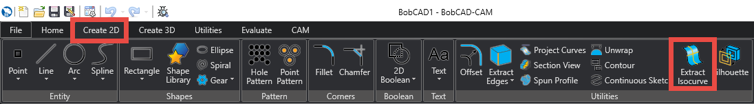
To use this function, select the 2D Design tab, in the upper right corner of this tab you will find the Extract Iso Curves icon.
Iso curves can be generated in the U-direction, V-direction, or both directions at the same time. U represents the direction of the surface and V perpendicular to the surface.
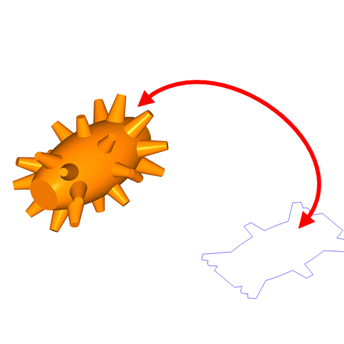
As you can see in the image, we now have 2D geometry that fully conforms to the surface, no matter how complex it is. This geometry is also very clean and can be used to address repairs, resurfacing and boundaries.
Silhouette
This function allows us to generate 2D contours from any type of solid element, including stereolithographies (STLs), thus opening the doors to the programming of elements that have been generated by point clouds in 3D scanners. Although our 3D strategies could read the STLs and generate toolpaths, it was impossible to define boundaries or generate 2D-like geometry from the STL. This forced us to create reference geometries that, on many occasions, did not coincide perfectly with our solid, making the programming process complex and imperfect.
The user can now select the Contour function in the 2D Design tab and from there select the solid, geometry orientation (using the method option) and axis direction for the silhouette. Once all these parameters are determined, the user will be able to generate 2D geometry from any type of solid or STL.
As you can see in the image, we have generated a 2D contour totally corresponding to the STL. Remember that the Silhouette function is executed on any user coordinate system, using any direction, in this way, we can generate contours from any position.
Advanced Holes
This function is very important, because it helps us in the design and programming processes. With it, the user can add properties to the holes, allowing the design of Reams (pockets) Threads (taps) and Chamfers (Countersinks), is just a matter of entering the necessary data in the Advanced Holes boxes and in real time, while adjusting the parameters of the Drills (bores), the modifications will be reflected in the design.
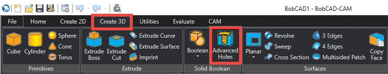
To use this feature, the user must create points in the center of each hole that they want to create, then look in the 3D Design tab for the Advanced Holes feature.
Once the function is active, select the points that represent the position of the holes (remember that the Z position of the points also affects the starting position of the holes) and define the type of hole you want to make, among the options of Enlarged (pockets), Threads (taps) and Chamfers (Countersunk).
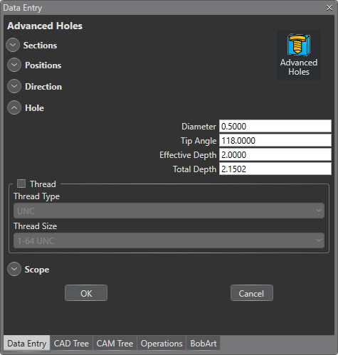
Then enter the parameters of the type of hole you selected, in the case of the flared ones, you must select the diameter and depth of this, for the chamfer, you must select the depth and the angle and for the threads, you must select the type of thread and its size. When all this information has been entered into the system, the user has a preview on the solid, to make sure that this is the result he is looking for.
When the parameters are correct, in addition to allowing you to define holes, BobCAD CAM now recognizes these properties directly in CAM, thus reducing hole programming time in parts designed in BobCAD or even in parts imported from other programs.
Also, it is important to highlight that all these drill parameters can be modified at any time, since the Advanced Holes are part of the CAD Manager, which allows the user to double-click on any drill and redefine its geometry, drilling properties. depth or type of hole.
We hope this blog helps you improve your management and knowledge our software.
Go here and sign up for our weekly training events, it’s Free!
Questions? Call Us to speak with a CAD CAM Pro!