When it comes to part programming with CAM software, drilling, profiles and pockets are some of the most common toolpaths you’ll use. These toolpaths are used even on 3D projects to rough and finish your part geometry. Let’s take a look at some of the features of BobCAD-CAM that help you with profiling.
Where is the profile feature?
After you’ve opened or created a design, you’ll create a new job and run the stock wizard to set up your stock geometry and your part zero. Once this step is done, you can start loading machining features into the CAM Tree and start programming your part.
You can choose your toolpath feature 1 of 2 ways. From the top navigation of the ribbon bar.

Or you can choose your toolpath feature by right-clicking on the machine setup.
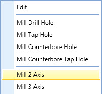
Either method will give you the toolpath feature categories to choose from. In our example, we want to look at profiling, so we will choose the Mill 2 Axis option.
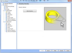
Once you’ve selected a toolpath feature, its wizard will launch. In our example, the Mill 2 Axis wizard will open and we will use it to define every aspect on the toolpath we are about to create. All the questions you’ll need to answer about tooling and settings are done through the wizard.
The first step is to select your geometry. You start this step by clicking on the select geometry button in the geometry selection window.
This will initiate BobCAD’s feature geometry picking manager. There are 3 main aspects to feature geometry picking.
1. Selecting your geometry
2. Selecting your start point and direction for profiles chains
3. Selecting your top and bottom of cutting.
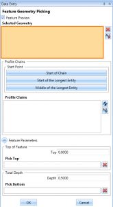
The feature geometry picking manager allows accomplishing all 3 settings in one streamlined workflow. This is unlike previous versions where some of these settings were defined in the Mill 2 axis wizard and some of these settings were defined in the CAM Tree.
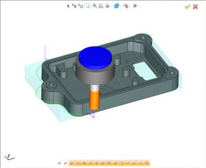
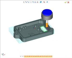
One huge advantage of the new Feature Geometry Picking manager is the preview displayed of your selected geometry. You’ll be able to visualize the depth settings and clearly see and change your geometry selection as needed.
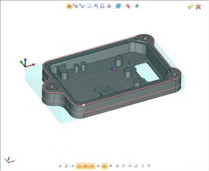
This is a very important part of correctly setting up your profile toolpath. You need to be aware of your Lead-in/out location of your part geometry and the direction of cut. Also, because of the preview, you can see where the cutting will start in Z and where it will end. There is no guessing if your settings are correct or not. Like the above example, we can clearly see the start arrow, the direction of cut and the depth. Because of the preview, we can see our depth is not correct because the red preview shows just before the bottom of the part. It’s visual aids like this that helps programmers get the most out of their CAM software by avoiding simple mistakes.
Note: 2 Axis machining features can be driven off wireframe, surface edges & surfaces. Users can single click on geometry, chain select for multiple connected pieces of geometry, select constant Z for surface edges or even loops. This makes working with a variety of CAD files and geometry types easier than earlier versions.
Now, I am sure you are aware of the 3 types of profile patterns BobCAD’s CAD-CAM offers, but just to make sure we’re all on the same page, let’s cover them really quick.
-Standard
-Contour Ramping
-Side Roughing
Using these 3 toolpath patterns, users can tackle all kinds of jobs and programming scenarios. You can machine closed and open shapes. You can also trim and extend your profiles within the wizard without needing to edit your geometry directly. Let’s take a look at some examples.
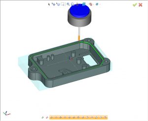
Standard Profile is used to walk your tool around part geometry, like in this example where we are walking around the outside of the part.

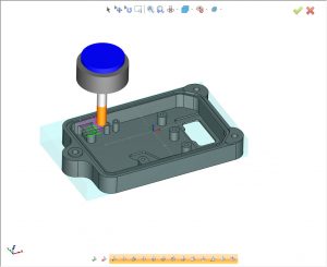
Or in this example where we are only profiling one side of the part.
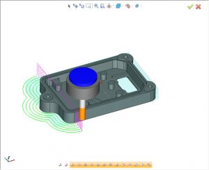
Contour Ramping
This pattern is used to ramp/helix your tool down following your part geometry. This is common for opening up holes, slots or just keeping your tool engaged with the material as it goes down in Z.
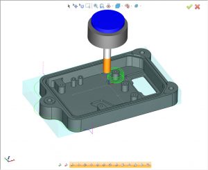
O ring groove sample programmed with contour ramp
Subscribe to BobCAD-CAM's CNC Software Blog
Join your fellow manufacturers! Get BobCAD-CAM’s latest CAD-CAM articles straight to your inbox. Enter your email below:
Side Roughing
This toolpath pattern is used to take multiple passes in XY. Allowing users to walk the tool into the part geometry, best used where additional material needs to be removed that can’t be taken in one pass.
Cutter Comp.
Now that we understand the geometry selection and toolpath patterns, let’s take a look at cutter compensation. BobCAD offers 2 types of compensation.
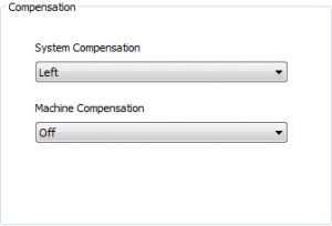
1. System Compensation
2. Machine Compensation
System compensation is where BobCAD will offset your profile by half the cutter size. BobCAD is doing the offset. Machine compensation is where G41/G42 are posted in your program, allowing users to adjust their offset at the control. G4/G42 typically has a D value. This D value is referenced to a table on the control that is used to adjust the offset.
What if you want to cut on center line?
You can turn both compensations off. When it comes to cutter comp., there are a few different approaches that are common.
1. System comp. off and machine comp. on.
Using this method your controller fully handles the compensation of the tool. This method allows users to change the tool size they are using at the control and be able to use the same NC program. The D value is used to define the full offset amount.
2. System comp. on and machine comp. on.
Using this method, BobCAD offsets for half the cutter and the machine comp. is used as an adjustment factor. More typically used as a smaller number to leave the wall “fat”, allowing the operator to measure the wall and adjust the offset to dial in the part tolerance. Users typically choose the compensation method they know and that has worked best for them on their parts.
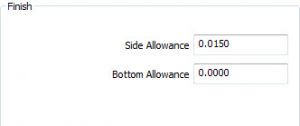
Depth Options
Using the Parameters page, users have additional adjustments they can use for their profile cutting. Such as leaving stock for the finish, both positive and negative amounts can be used here.
When it comes to your depth of cut, users can program a single depth or they can use multiple steps. BobCAD offers 2 depth step options:
1. Even depths
2. Defined depths
Even depth will adjust the depth of cut increment so that an even amount is used to reach the total depth. Defined depths will adjust the last increment of cut to machine what’s left over from the defined depth.
When cutting profiles with multiple depths of cut, users can also choose minimize retracts to keep the tool from going to clearance between each depth of cut. Also referred to as “ keep tool down”.
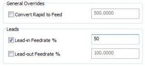
Advanced Feedrates
Get more control to your feedrates during specific points of the profile. Now users have control to adjust the feedrate value at the Lead-in and out of profile. So, if the tool is making a heavy cut as it enters the part you can slow the feedrate down during this lead-in move. Additional feedrate control is something you’ll notice more of in the BobCAM software.
So, there you have it. Whether you are doing drilling, profiling or pocketing, these are the features that will be most beneficial to you in your machining process. Make sure to sign up in the newsletter form to get articles just like this delivered to your email!
Start your Test Drive.
Have questions? Call us at 877-838-1275.
You’re one click away from subscribing to BobCAD’s YouTube channel. Click the link below for tips, how-tos and much more!
To see if BobCAD’s Mill Turn software is right for your shop,