Questions? Call Us to speak with a CAD CAM Pro!
Tech Tuesday is a weekly blog that addresses some of the most common questions and concerns that I hear throughout the previous week from users of BobCAD’s CNC software. Both customers and future customers are more than welcome to leave a comment on what they would like to see covered for the following Tech Tuesday.
Today’s Tech Tuesday will take a look at the drilling/hole making cycles BobCAD-CAM’s CAD-CAM software offers and the powerful built-in calculators that makes hole set up and programming faster and easier.
Do you know the role geometry selection play when drilling holes?
Keep reading to find out how you can use different geometry types to drive your drilling cycles.
Let’s get started by taking a look at the drilling/hole making cycles BobCAD offers and some of the calculators that are built in that make it easier to set up and program your holes.
Mill Drill Hole Feature
BobCAD’s Mill Drill Hole Feature allows you to select hole location(s) and apply multiple operations at one time.
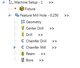
You can choose from 6 operations to process your holes:
Center Drill: Used to spot drill hole locations, center, center chamfer, or center countersink.
Example:
N2 T1 M06
N3 G00 G90 G54 X0. Y0.
N4 G43 H1 S4435 M03
N5 Z2.9685 M08
N6 Z2.1685
N7 G81 G98 X0. Y0. Z1.8885 R2.0685 F12.75
N8 G80
N9 G00 Z2.9685
N10 M09
N11 M05
Drill: Used to drill holes with standard or pecking cycles
Example:
N12 T2 M06
N13 G90 G54 X0. Y0.
N14 G43 H2 S7761 M03
N15 Z2.9685 M08
N16 G00 Z2.1685
N17 G83 G98 X0. Y0. Z1.3434 R2.0685 Q.125 F22.31
N18 G80
N19 G00 Z2.9685
N20 M09
N21 M05
Chamfer Drill: Used to add a chamfer to the hole using a chamfer drill.
Example:
N22 T3 M06
N23 G90 G54 X0. Y0.
N24 G43 H3 S2587 M03
N25 Z2.9685 M08
N26 G00 Z2.1685
N27 G81 G98 X0. Y0. Z1.8335 R2.0685 F7.44
N28 G80
N29 G00 Z2.9685
N30 M09
N31 M05
Chamfer Mill: Used to add a chamfer to the hole using a chamfer mill. The tool follows the hole profile.
Example:
N32 T4 M06
N33 G00 G90 G54 X.0425 Y0.
N34 G43 H4 S3880 M03
N35 Z2.9685 M08
N36 G00 Z2.1685
N37 Z2.0685
N38 G01 Z1.9385 F11.16
G03 X-.0425 Y0. I-.0425 J0. F22.31
G03 X.0425 Y0. I.0425 J0.
N39 G00 Z2.1685
N40 Z2.9685
N41 M09
N42 M05
Ream: Used to ream a hole using a reaming cycle
Example:
N43 T5 M06
N44 G00 G90 G54 X0. Y0.
N45 G43 H5 S7761 M03
N46 Z2.9685 M08
N47 G00 Z2.1685
N48 G81 G98 X0. Y0. Z1.4185 R2.0685 F17.85
N49 G80
N50 G00 Z2.9685
N51 M09
N52 M05
Bore: Used to bore a hole using a boring cycle
Example:
N53 T6 M06
N54 G90 G54 X0. Y0.
N55 G43 H6 S7761 M03
N56 Z2.9685 M08
N57 G00 Z2.1685
N58 G86 G98 X0. Y0. Z1.4185 R2.0685 F33.47 P1.2
N59 G80
N60 G00 Z2.9685
N61 M05
N62 M09
Utilizing BobCAD’s Built-In Calculators
Center Drill / Spot Drill Operation:
Typically before you drill a hole you’ll center drill/spot drill the hole.
Using the center drill operation, users can just spot a hole, chamfer the hole or even create a counter skin.
With the proper tooling selected, users can take advantage of BobCAD’s built-in calculator to define the center depth, the center hold diameter or the center angle.
As you make adjustments to one parameter, the other values will update.
The calculator is simple to use and very handy.
Example:
Let’s say you need to drill some ¼” holes and the print calls out for a .015 edge break.
One way you can accomplish this edge break is with your spot tool.
By using BobCAD’s built-in calculator, you can enter the desired center hole diameter and BobCAD will calculate the proper depth to create the hole’s chamfer.
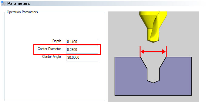
With the correct tooling selected, use BobCAD’s calculator to define your spot/center drill depth.
In this example above, we entered the desired center diameter and the software calculated the proper depth for us.
Drill Tip Compensation:
Now that’s we’ve centered or spot the hole, let’s talk about the drill tip calculator you’ll find in the Drill Operation Parameters.
You’ll notice on the operations parameters page for the drill cycle a few different things.
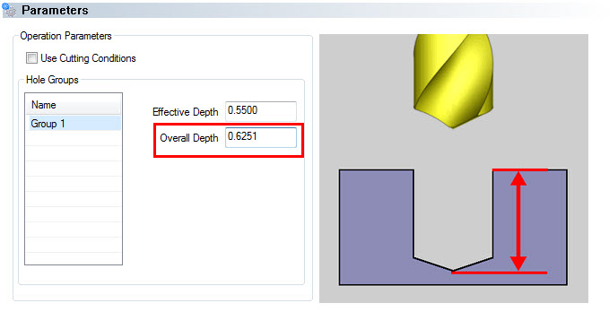
At the top, you have the checkbox for use cutting conditions.
By unchecking this box, you can override the drill depth settings.
If you are drilling holes of the same size that start and stop at different depths, you can select the hole group you want to update the depth settings for.
(We’ll get into hole groups and how to use them in a future blog post.)
For now. let’s focus on the effective depth and the overall depth values.
You’ll notice one value is different from the other.
This is due to BobCAD’s Drill Tip Compensation Calculator.
Based on the drill tip angle of your selected tool, BobCAD calculates the effective depth (drill depth lesser the tip angle.)
The overall depth is the value that will be posted in your G-code.
If you update the effective depth, the overall depth will be compensated for the drill tip.
BobCAD provides another handy & simple to use calculator for drilling.
Geometry Selection For Holes:
Now that we’ve reviewed the built-in calculators, you can use to adjust your center and drill depths let’s talk about geometry selection.
When it comes to drilling holes you can select:
- Points
- Arcs
- Surface Edges
- Surfaces
When selecting geometry for your holes, you’ll notice an option for Point and Arc Usage options:
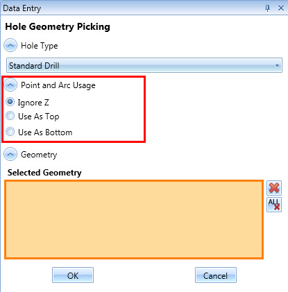
This powerful and often overlooked option provides you more control over how BobCAD will use not only the X & Y locations of your selected geometry but their Z position.
- Ignore Z
- Use As Top
- Use As Bottom
Your selection of the point and arc usages give you control over how the Z position of your selected geometry is used.
For example, you could select points or arcs at the Z position you want to either drill or begin drilling allowing users to leverage their geometry selecting to drive their drill cycle.
And this is just another of the handy and simple to use features BobCAD offers for drilling.
To learn more about 2D Drilling with BobCAD, make sure to join the BobCAD After Dark Facebook group.
We host weekly live videos covering topics like this and much more.

BobCAD-CAM has provided CAD-CAM CNC Software products to the global manufacturing industry for over 30 years. BobCAD-CAM software can be found to increase CNC productivity for many applications in aerospace, automotive, production manufacturing, mold making, general machining, woodworking as well as the medical manufacturing industry, consumer products, musical instruments, custom fabrication, defense industry and many others due to the products ability to automatically generate NC programming code for such a wide variety of CNC controllers. BobCAD-CAM software is also found in educational institutions throughout the world as well as independent hobby home use. Products include machining technology for 2, 3, 4 & 5 Axis CNC Milling, Routing, Waterjet, Plasma and Laser machines as well as 2 Axis CNC Lathe. BobCAD-CAM is modular allowing shops to start off at a reduced technology level and add technology as it is needed including an add-on, BobART, for artistic machining. Unique technology includes adaptive high-speed machining multiaxis milling and routing which is a first in the world of CAD-CAM software. BobCAD-CAM also provides a variety of quality training products that include regional and online training classes or private sessions tailored to specific applications. Professional certification and multi-tiered support solutions are available.
Questions? Call Us to speak with a CAD CAM Pro!