 The ability to add text, logos, or other 2-dimensional design work to 3-dimensional parts can be a vital function for a variety of CNC businesses and independent machinists. Everyone from sign makers, jewelry manufacturers, custom woodworkers, and beyond can find themselves in a position of needing or wanting to add text, logos, or 2D images to their parts. Using CAD/CAM software to properly pocket out material from curved surfaces can be complex. Not only do you need to wrap a 2D image around a 3D model but you also need to account for tool geometry to avoid gouging the part on the curve.
For many, the only option in CAD/CAM software is to generate a toolpath for the wireframe geometry from text or a logo and project the toolpath down onto the surface curve. Doing this, the wireframe and toolpath wraps tightly to the surface geometry. Initially this might seem to be a perfect solution and it can be for a flat surface. However, this method does not take into account the diameter of the actual tool so it often results in part gouging along a curved surface. So this method isn’t an effective way to engrave or pocket material from text or a logo onto a curve.
Advanced CAD/CAM Software Feature
Thanks to the PROJECT CURVES function within Version 27 Professional of BobCAD-CAM, users can now compensate for the cutter.
Instead of projecting toolpaths from text or logo wireframe geometry onto a surface, you can use PROJECT CURVES to wrap the wireframe geometry onto the surface curve. Using the machining wizard, you’ll set up your toolpaths on the surface. The main difference here is that the PROJECT CURVES machining strategy asks you to supply your tool specs so that the CAD/CAM software can automatically calculate the proper toolpath offset distance from your surface to avoid part gouges.
Example:
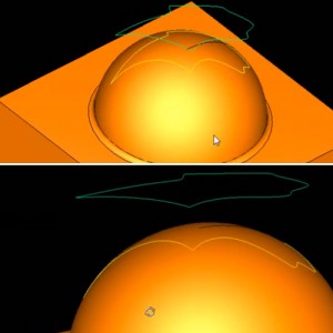
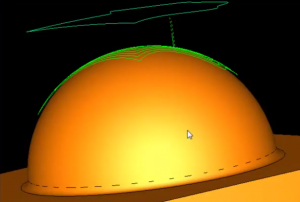 Say you have a logo like we have in the pictures to the right. We’ve converted the logo into a wireframe boundary, which is floating above our curve. Using the PROJECT CURVES machining strategy we select our wireframe geometry from our logo and our surface curve to project the logo boundaries down onto the surface. Once we’ve done this, we’ll have the ability to set up how we want our toolpath to cut, the number of cuts, and if our cuts will go inside the boundaries, outside the boundaries, or both. These options are found under the Patterns menu of the machining Wizard of our PROJECT CURVES operation in the CAD/CAM software.
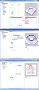 By default, the toolpath won’t actually cut into the surface. We’ll need to set a negative allowance to have the tool cut down into the surface. We would set this up under the Parameters menu of the machine wizard for our PROJECT CURVES operation.
PROJECT CURVES gives you the ability to easily add logos and text to 3D surfaces. Whether you’re looking to completely pocket out the material, cut a border, or give your text or logo an embossed look, this tool has the power to properly machine your job.
Try this out for yourself with a free, no obligations trial copy of the BobCAD-CAM software today. CLICK HERE TO DOWNLOAD
Here are some other articles you may be interested in:


Summary
Article Name
Use CAD/CAM Software to Easily Project Text & Logos onto Curved Surfaces
Description
Learn how to apply 2D wireframe geometry to a curved surface and properly set up toolpaths that compensate for the cutter.
Author
Nick Erickson | BobCAD-CAM