Tech Tuesday is a weekly blog that addresses some of the most common questions and concerns that I hear throughout the previous week from users of BobCAD-CAM software. Both customers and future customers are more than welcome to leave a comment on what they would like to see covered for the following Tech Tuesday. Enjoy!
So, how do you turn that picture you love into vectorized geometry capable of being machined? With BobCAD-CAM’s premier artistic CAD-CAM software of course! Transform your artistic imagination into manufacturing reality with any CNC Mill, Router, Waterjet, Laser or Burning machine. Let’s take a look at how we go from picture to perfect with BobART.
The BobART Manager
Loading Images, Vector Files or BobART (.bart) Files
The “BobART Manager” item in the BobART Tree features shortcuts for loading images, vector files or BobART (.bart) files. Right-click “BobART Manager” in the menu for the following commands:
- Load Images- Put any image of your choosing here. Users will select a file type, then select and open an image file. The image will then be displayed in the graphics area and the feature tree is added under Images to be vectorized.
- Load BobART Pro-X (.bart) File- This function allows you to choose and open your .bart file. There will be an embossed model displayed in the graphics area and the feature is added under Emboss Model.
- Load Vector Files- This function lets users select and access a vector graphics file of the supported file extensions: .ai, .eps and .pdf. Vectorized geometry will be loaded into the graphics area for editing and used for embossed models or CAM features.
Subscribe to BobCAD-CAM's Tech Tuesday Blog
Join your fellow machinists. Get the latest Tech Tuesday CAD-CAM articles sent to your inbox. Enter your email below:Vectorizing Images
Vectorizing images means you are creating wireframe geometry from an image based on the location and color of pixels located in the image. After the raster-to-vector conversion, the geometry that’s created can be modified and used to create embossed models or Milling features. This process involves loading an image and defining the vectorization strategy
There are 2 strategies users can choose from when vectorizing images. Either 2-Level Black/ White or Multi-Color Strategy; let’s take a look at them individually.
2-Level Black/ White Strategy
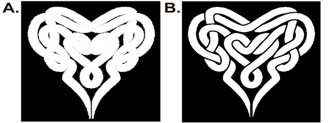
Users who select this option will set their image up using the Threshold Value function to determine vectorization based on the grayscale range of 1-255. Next, you will either type in a value in the Threshold Value box or you can use the Threshold Value slider to find your perfect fit. There will be a preview window to the right to view your current setting. The minimum value of 1 will result in an all-white preview, and the maximum value of 255 will result in an all black preview. The images below demonstrate how each value affects the image. Image “A” is set at a threshold value of 4 while image “B” is increased to a value of 150. As you can see, image “B” is cleaner and made the picture more defined for vectorization.
Multi-Color Strategy
- Number of Colors- This feature sets the number of colors used for vectorization. Numbers range from a minimum of 3 colors to a maximum of 64. They will display in the Colors to be Vectorized group.
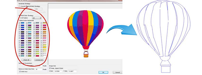
The advantage of using Multi-Color Strategy to vectorize geometry is that the user can turn different colors on and off to save pieces of vectorized geometry on multiple different layers. This comes in handy for jobs that are complex and highly detailed. Users can change the Vectorization Parameters but may want to use the default until previewing the results and adjusting accordingly. It’s important to remember when vectorizing an image more than once to create a copy of any wireframe geometry you want to keep so the software doesn’t replace it on the next vectorization. When you are happy with your parameters that you set then click OK. As you finish vectorization, you can use the sketch geometry for CAM features or emboss models. Thank you for reading the very first Tech Tuesday; keep an eye out for many more!

You’re one click away from subscribing to BobCAD’s YouTube channel. Click the link below for tips, how-tos and much more!
BobCAD-CAM has provided CAD-CAM CNC Software products to the global manufacturing industry for over 30 years. BobCAD-CAM software can be found to increase CNC productivity for many applications in aerospace, automotive, production manufacturing, mold making, general machining, woodworking as well as the medical manufacturing industry, consumer products, musical instruments, custom fabrication, defense industry and many others due to the products ability to automatically generate NC programming code for such a wide variety of CNC controllers. BobCAD-CAM software is also found in educational institutions throughout the world as well as independent hobby home use. Products include machining technology for 2, 3, 4 & 5 Axis CNC Milling, Routing, Waterjet, Plasma and Laser machines as well as 2 Axis CNC Lathe. BobCAD-CAM is modular allowing shops to start off at a reduced technology level and add technology as it is needed including add-ons for artistic machining and nesting sheet optimization. Unique technology includes adaptive high-speed machining multiaxis milling and routing which is a first in the world of CAD-CAM software. BobCAD-CAM also provides a variety of quality training products that include regional and online training classes or private sessions tailored to specific applications. Professional certification and multi-tiered support solutions are available. Contact BobCAD-CAM directly for more information at 877-262-2231 or 727-442-3554.


I am an Ag. Teacher in Oklahoma, I have a PlasmaCam Table. I am looking for software that I can upload an image, trace it with my mouse and convert the sketch into a DXF file. Does BobCAD-CAM have any thing that can help?
Thank you for your question, Lee. Yes, BobART can import an image (raster file) or PDF (vector file). Once imported, the user can vectorize the image if it is good quality which creates CAD data from the image. Or, if the image is bad quality the user can trace the image using the CAD tools. Learn more about BobART here: https://bobcad.com/products/bobart-v28-artistic-cad-cam/?source=ART_TOPNAV