Assigning a Fixture
Introduction
Each of the machine setups in a milling job can have a unique fixture assigned to it.This example explains how to assign components as a fixture in a machine setup.In this example, once we assign the fixture, we will also view the fixture in simulation.
This example will have you:
- Assigning the Fixture
- Simulate the Milling Job
Example Part
If you are connected to the Internet, the part file for this example can be downloaded automatically by clicking the following link: SlottedPart_and_FixtureSub1.sldprt
Once you download and saved the zip file, extract the files on your system in an easy place to remember.You can then open the file to use with this tutorial.All files for the tutorials in this help system available for download can be found by clicking on the following link: http://www.bobcad.com/helpfiles.
Note: In this example we have setup a part with a vice we want to assign for a fixture.The job has already been created.
| Machine Setup 1 |
|
Important: If, when the assembly is open, the parts in the Feature Manager Design Tree show an ![]() icon, right-click
icon, right-click ![]() Part Name at the top of the Feature Manager Design Tree, and select Set Lightweight to Resolved.The part icons will then show an
Part Name at the top of the Feature Manager Design Tree, and select Set Lightweight to Resolved.The part icons will then show an ![]() icon, and you will then have access to the part features.
icon, and you will then have access to the part features.
Part 1) Assigning the Fixture
With everything in the job completed already, we could simply simulate, and post out the code.However, in order to see the fixture in the simulation, and check it for collisions, we will need to assign geometry as our fixture.
- Click the
 BobCAM Manager tab.
 - Click the
 icon next to
  Machine Setup - 1 in order to expand it.
 - Right-click
 Fixture, and select Re/Select.
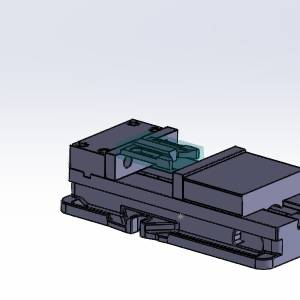
The Fixture dialog appears with focus on the Solid Body list. - Select each component of the vise.
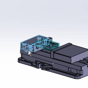
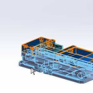
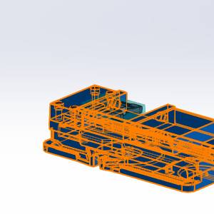
Note: In the images above the bolts on top of the fixed jaw, and the vise handle mount are not selected.Since the fixture selection is used to check for collisions in the simulation, you may choose to leave particular aspects of the vise assembly unselected.
- Click
 (OK).
(OK).
The Fixture dialog closes, and the icon is no longer seen in front of the Fixture item in the CAM Tree.This shows that geometry is currently assigned.
Part 2) Simulate the Milling Job
With the fixture assigned, we can now view it in the simulation.
- Right-click the
 Milling Job, and select Simulation.
The simulation launches. - Click
 Run.
Run.
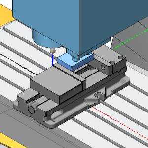
Notice the fixture is visible in the simulation.With the fixture assigned, collisions with it and other components in the simulation will be reported.
| Machine Setup - 1 |
|
- Click
 (Exit) at the top right of the simulation window to close the simulation.
This concludes this example.