CAD-CAM software has everything to do with modern CNC machine programming and plays a critical role in the future success of manufacturing at a global level. Manufacturers are continuously looking for solutions to improving CNC automation that is efficient, safe and takes the most profitable route to making parts.
When it comes to CAD-CAM programming, the programmer/operator can look at a part model and determine the right machining strategies that will lead to a finished part and then heavily relies on computer-aided machining software capabilities to get the right results. This is where a quality CAM system that offers the widest variety of 2D & 3D cutting strategies becomes the winner. Determining the best 2D vs. 3D cutting Toolpath strategies is easier than you might think, yet still commands a certain level of training to fully understand how the operations work and the results that can be achieved by using them.
Subscribe to BobCAD-CAM's CNC Software Blog
Join your fellow manufacturers! Get BobCAD-CAM’s latest CAD-CAM articles straight to your inbox. Enter your email below:

Look for cost-effective CAD-CAM that provides:
2D Machine Toolpath Strategies
3D Machine Toolpath Strategies
Simulation
NC Editor
Customizable Post Processing
Excellent Training
Understanding 2D CAM Programming
2D Toolpaths are based on wireframe*. Generally, if you are drawing a part from scratch you use points lines and arc to create your geometry. Once you’ve drawn the features you need to machine in the part you’ll apply 2D toolpaths for machining.
2D Wire Frame types used in CAM include:
Points
Lines
ARCS
Other Shapes
Splines
These types of geometries can be used for drawing profiles to be machined and more that include boundary geometry that is used to contain toolpath into a specific region of a part model.
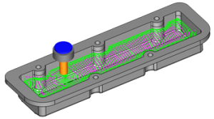
2D CAM Programming Operations:
Drilling
Facing
Profile
Pocketing
Thread Milling
Engraving
Chamfer
Corner Rounding
Plunge Rough
These machining operations are available through Dynamic Machine Strategy™ functionality where the user can use multiple operations for individual CAD features. This streamlines creating the machining operations and simplifies the process as the user can get more done in less CAM moves.
Note that if you’ve imported a file or choose to create a solid model of your part you can use surface edges as boundaries for 2D toolpaths, and you can use surface edges to define the depth of your Toolpaths.
Understanding 3D CAM Programming
3D drawings mostly are based on wireframe boundaries that are used to create surfaces or solids. There are Surfacing / Solids features that do not require any wire fame, they use user input as an example, primitive solids shapes. Also, you can use surface edges to create additional surfaces or solids.
3D geometry types and functionality used to create Surfaces include:
Rectangular Plane
Circular Plane
Planar
Extrude Curve
Extrude Surface
Revolve
Sweep
Cross Section
Skin
Offset
3 Edge
4 Edge
Multisided Patch
Fillet
Swung
Ruled
3D primitive Solids include:
Sphere
Cube
Code
Cylinder
Torus
Fillet
Primitive solids are used in combination with solid Boolean editing features to create solid models.
3D Surface /Solid Editing Features: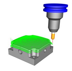
Add
Subtract
Intersect
Split
Shell
Extrude Boss
Extrude Cut
Extend
Intersection Curves
Untrim Surface
Break Surface
Section
Scale
Now that you have a 3D surface or solid you can apply 3D toolpath to them. 3D toolpath cut where and to the surfaces you have selected. So unlike 2D toolpath where you define a boundary and depth, 3D Toolpaths are applied to the model directly, where they cut and how deep is based on the surface or solid directly.
3D Toolpaths Surface that are Solid Based:
Z Level Rough
Z Level Finish
Planar
Spiral
Radial
Plunge Rough
Advanced Rough
Flatlands
Equidistant offset
Pencil
Advanced Planar
Project Curves
Advanced Z Level Finish
3D Toolpaths that are Surface Based Only: 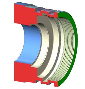
Parallel Cuts
Cuts Along Curve
Morph Between 2 Curves (Flowline style machine toolpath)
Parallel To Multiple Curves
Project Curves
Morph Between 2 Surfaces
Parallel To Surface
Cutting options you use in 3D Toolpaths affect where Toolpath is created. Toolpaths are created based on the model surfaces you’ve selected, and depending on the cutting options for that Toolpath like the stock for finish, DOC, boundary, operational stock, surfaces you’ve select to avoid ( check surfaces ) affect where material s left over or targeted for cleanup.
2D CAD-CAM will always have a place in machine shops for CNC machine programming. 3D CAD-CAM allows shops to efficiently manufacture complex geometry and handle harder jobs with much success.
NOTE: All of the information in this article is available as functionality in BobCAD-CAM Software. The Advanced Roughing, REST, High-Speed Adaptive Roughing and advanced Machine Simulation are available in the Mill 3 Axis PRO version of the software.

BobCAD-CAM has provided CAD-CAM CNC Software products to the global manufacturing industry for over 30 years. BobCAD-CAM software can be found to increase CNC productivity for many applications in aerospace, automotive, production manufacturing, mold making, general machining, woodworking as well as the medical manufacturing industry, consumer products, musical instruments, custom fabrication, defense industry and many others due to the products ability to automatically generate NC programming code for such a wide variety of CNC controllers. BobCAD-CAM software is also found in educational institutions throughout the world as well as independent hobby home use. Products include machining technology for 2, 3, 4 & 5 Axis CNC Milling, Routing, Waterjet, Plasma and Laser machines as well as 2 Axis CNC Lathe. BobCAD-CAM is modular allowing shops to start off at a reduced technology level and add technology as it is needed including an add-on, BobART, for artistic machining. Unique technology includes adaptive high-speed machining multiaxis milling and routing which is a first in the world of CAD-CAM software. BobCAD-CAM also provides a variety of quality training products that include regional and online training classes or private sessions tailored to specific applications. Professional certification and multi-tiered support solutions are available. Contact BobCAD-CAM directly for more information at 877-262-2231 or 727-442-3554.