Tool Page
Introduction
This topic serves to describe the various tool pages available, and will provide links to related topics.
The Tool Page
From this tool page, you can either, choose a different tool from the Tool Crib, go into the Tool Crib to add tools from your Tool Library, or enter tool specific data manually into the Tool Data Section of the page. This page will also assist in assigning Tool Numbers and Offsets, and Coolant options, as well as Speeds and Feeds.
Tip: It is good practice to have all the tools for the job loaded into the Tool Crib at the start of the job. If you do, the tools for the job will already be in the Tool Crib, and the system will have pulled appropriate tools for each operation from the Tool Crib.
- Tool Crib - opens the Tool Crib for you to select a tool
that you have already loaded for the job. Click to select a tool in the
tools list, and click OK to assign the tool to the operation. (For Mill
Turn jobs, view Mill Turn Tool Crib.
- Assign/Edit Tool Holder - Assign Tool Holder opens the Milling Tool Holder Library to assign a tool holder to the tool. In the Tool Holder list on the right, select a tool holder/arbor, then click OK. The name of the selected tool holder appears in the Holder Label box. This holder is now the default tool holder for the tool, meaning that it is automatically assigned to the tool when you create an operation with this tool. Edit Tool Holder opens the Tool Holder Definition dialog.
Tool Data
To select a tool for the feature you can use the following option in one of two ways.
- System
Tool
 Select this check
box to allow the software to automatically select tools from the Tool
Crib that match the machining
operation. In the case of end mills, you may alter the diameter and corner
radius allowing the software to find the appropriate tool from the Tool
Crib. In the case the appropriate tool sizes are not found, the software
searches for a matching tool in the Tool Library. If a matching tool is
found, it is added to the Tool Crib. If a matching tool is not found,
a new tool is automatically created and added to the Tool Crib.
Select this check
box to allow the software to automatically select tools from the Tool
Crib that match the machining
operation. In the case of end mills, you may alter the diameter and corner
radius allowing the software to find the appropriate tool from the Tool
Crib. In the case the appropriate tool sizes are not found, the software
searches for a matching tool in the Tool Library. If a matching tool is
found, it is added to the Tool Crib. If a matching tool is not found,
a new tool is automatically created and added to the Tool Crib. When this check
box is cleared, you can edit all tool information directly in the dialog
box. In this case, the defined tool is added to the Tool Crib.
When this check
box is cleared, you can edit all tool information directly in the dialog
box. In this case, the defined tool is added to the Tool Crib.
Note: Although the Machining Data group remains the same regardless of the tool selected, The available Tool Data, and the Speed and Feed parameters vary depending on the type of tool selected. Click on a tool to display the Tool Data for that particular tool. Once open, click on Machining Data and Feeds and Speeds to see the corresponding variables.
Important: Historically the coolant option found in the tool page has been a drop down which allowed you to select from Off, Flood, Mist, Air, or Oil and refers to posting blocks 673, 674, and 706 through 708. Starting in version 34 a Coolant group was added to the Machine Parameters page of the Current Settings dialog. This allowed you to use the new coolant options and refers to the new posting blocks 840-859. With the Use customized coolant options check box selected in the Current Settings, the Coolant options launches a dialog allowing you to select which coolant options are turned on for this operation. Please note that post updates may be required to utilize the newer options.
Drill
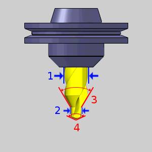
 Center Drill
The following items are displayed for informational purposes:
|
|
Machining Data
The Machining Data parameters change slightly depending on whether you are in a Turning job or Mill Turn job. All parameters are explained next.
-
Tool Number - opens the Assigned Tools dialog box for you to change the tool numbering.
-
Override Offsets
![]() Clear the Override Offsets check box to use the tool number to set the
Offset Register value.
Clear the Override Offsets check box to use the tool number to set the
Offset Register value.
![]() Select the Override Offsets check box to allow for manual editing of the
Offset Register value.
Select the Override Offsets check box to allow for manual editing of the
Offset Register value.
- Height Offset - sets
the Height Offset to be used in the posted program.
- Diameter Offset - sets the Diameter Offset to used in the posted program.
Spindle Direction
-
 CW - sets the spindle direction to clockwise.
 -
 CCW - sets the spindle direction to counterclockwise
- Coolant - sets the coolant on code(s) which will be output for the operation. (See the note at the top of the topic for more information on the coolant options)
Feeds and Speeds
By default, the software automatically calculates feeds and speeds based on the values defined in the Stock Material Library.
- Use System
Feeds and Speeds
Select this check
box to automatically calculate the feeds and speeds. Clear this check
box to type feeds and speeds values in the dialog box. - SFM/SMM - is the surface feet/meters per minute feedrate.
- Plunge Feed per Tooth - sets the rate of depth per tooth. The value is linked to the Plunge Feedrate.
- Spindle RPM - is the revolutions per minute of the spindle.
- Plunge Feedrate - is the downward feedrate. This value is linked to the Plunge Feed per Tooth.
- Dwell - sets the amount of seconds to Dwell.
Note: While editing the feeds and speeds, changing one value automatically calculates any other associated values. For example, if you modify the SFM value, the Spindle RPM, Cutting Feedrate, and Plunge Feedrate are automatically calculated.
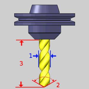
Drill
The following items are displayed for informational purposes:
|
|
Machining Data
The Machining Data parameters change slightly depending on whether you are in a Turning job or Mill Turn job. All parameters are explained next.
-
Tool Number - opens the Assigned Tools dialog box for you to change the tool numbering.
-
Override Offsets
![]() Clear the Override Offsets check box to use the tool number to set the
Offset Register value.
Clear the Override Offsets check box to use the tool number to set the
Offset Register value.
![]() Select the Override Offsets check box to allow for manual editing of the
Offset Register value.
Select the Override Offsets check box to allow for manual editing of the
Offset Register value.
- Height Offset - sets
the Height Offset to be used in the posted program.
- Diameter Offset - sets the Diameter Offset to used in the posted program.
Spindle Direction
-
CW - sets the spindle direction to clockwise.
-
CCW - sets the spindle direction to counterclockwise
- Coolant - sets the coolant on code(s) which will be output for the operation. (See the note at the top of the topic for more information on the coolant options)
Feeds and Speeds
By default, the software automatically calculates feeds and speeds based on the values defined in the Stock Material Library.
- Use System
Feeds and Speeds
Select this check
box to automatically calculate the feeds and speeds. Clear this check
box to type feeds and speeds values in the dialog box. - SFM/SMM - is the surface feet/meters per minute feedrate.
- Plunge Feed per Tooth - sets the rate of depth per tooth. The value is linked to the Plunge Feedrate.
- Spindle RPM - is the revolutions per minute of the spindle.
- Plunge Feedrate - is the downward feedrate. This value is linked to the Plunge Feed per Tooth.
- Dwell - sets the amount of seconds to Dwell.
Note: While editing the feeds and speeds, changing one value automatically calculates any other associated values. For example, if you modify the SFM value, the Spindle RPM, Cutting Feedrate, and Plunge Feedrate are automatically calculated.
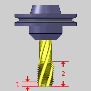
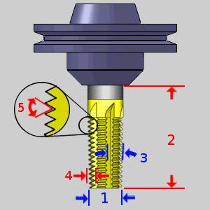
Spiral Tap
The following items are displayed for informational purposes:
|
|

Machining Data
The Machining Data parameters change slightly depending on whether you are in a Turning job or Mill Turn job. All parameters are explained next.
-
Tool Number - opens the Assigned Tools dialog box for you to change the tool numbering.
-
Override Offsets
![]() Clear the Override Offsets check box to use the tool number to set the
Offset Register value.
Clear the Override Offsets check box to use the tool number to set the
Offset Register value.
![]() Select the Override Offsets check box to allow for manual editing of the
Offset Register value.
Select the Override Offsets check box to allow for manual editing of the
Offset Register value.
- Height Offset - sets
the Height Offset to be used in the posted program.
- Diameter Offset - sets the Diameter Offset to used in the posted program.
Spindle Direction
-
CW - sets the spindle direction to clockwise.
-
CCW - sets the spindle direction to counterclockwise
- Coolant - sets the coolant on code(s) which will be output for the operation. (See the note at the top of the topic for more information on the coolant options)
Feeds and Speeds
By default, the software automatically calculates feeds and speeds based on the values defined in the Stock Material Library.
-
Use System Feeds and Speeds
![]() Select this check
box to automatically calculate the feeds and speeds.
Select this check
box to automatically calculate the feeds and speeds.
![]() Clear this check
box to type feeds and speeds values in the dialog box.
Clear this check
box to type feeds and speeds values in the dialog box.
- SFM/SMM - is the surface feet/meters per minute feedrate.
- Spindle RPM - is the revolutions per minute of the spindle.
- Feed per Minute - is the feedrate for the tap in feed per minute.
- Feed per Revolution - is the total depth per revolution.
-
Dwell - sets the amount of seconds to Dwell.
Note: While editing the feeds and speeds, changing one value automatically calculates any other associated values. For example, if you modify the SFM value, the Spindle RPM, Cutting Feedrate, and Plunge Feedrate are automatically calculated.
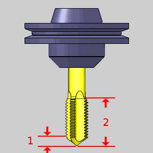
Point Tap
The following items are displayed for informational purposes:
|
|
Machining Data
The Machining Data parameters change slightly depending on whether you are in a Turning job or Mill Turn job. All parameters are explained next.
-
Tool Number - opens the Assigned Tools dialog box for you to change the tool numbering.
-
Override Offsets
![]() Clear the Override Offsets check box to use the tool number to set the
Offset Register value.
Clear the Override Offsets check box to use the tool number to set the
Offset Register value.
![]() Select the Override Offsets check box to allow for manual editing of the
Offset Register value.
Select the Override Offsets check box to allow for manual editing of the
Offset Register value.
- Height Offset - sets
the Height Offset to be used in the posted program.
- Diameter Offset - sets the Diameter Offset to used in the posted program.
Spindle Direction
-
CW - sets the spindle direction to clockwise.
-
CCW - sets the spindle direction to counterclockwise
- Coolant - sets the coolant on code(s) which will be output for the operation. (See the note at the top of the topic for more information on the coolant options)
Feeds and Speeds
By default, the software automatically calculates feeds and speeds based on the values defined in the Stock Material Library.
-
Use System Feeds and Speeds
![]() Select this check
box to automatically calculate the feeds and speeds.
Select this check
box to automatically calculate the feeds and speeds.
![]() Clear this check
box to type feeds and speeds values in the dialog box.
Clear this check
box to type feeds and speeds values in the dialog box.
- SFM/SMM - is the surface feet/meters per minute feedrate.
- Spindle RPM - is the revolutions per minute of the spindle.
- Feed per Minute - is the feedrate for the tap in feed per minute.
- Feed per Revolution - is the total depth per revolution.
-
Dwell - sets the amount of seconds to Dwell.
Note: While editing the feeds and speeds, changing one value automatically calculates any other associated values. For example, if you modify the SFM value, the Spindle RPM, Cutting Feedrate, and Plunge Feedrate are automatically calculated.
Hand Tap
The following items are displayed for informational purposes:
|
|
Machining Data
The Machining Data parameters change slightly depending on whether you are in a Turning job or Mill Turn job. All parameters are explained next.
-
Tool Number - opens the Assigned Tools dialog box for you to change the tool numbering.
-
Override Offsets
![]() Clear the Override Offsets check box to use the tool number to set the
Offset Register value.
Clear the Override Offsets check box to use the tool number to set the
Offset Register value.
![]() Select the Override Offsets check box to allow for manual editing of the
Offset Register value.
Select the Override Offsets check box to allow for manual editing of the
Offset Register value.
- Height Offset - sets
the Height Offset to be used in the posted program.
- Diameter Offset - sets the Diameter Offset to used in the posted program.
Spindle Direction
-
CW - sets the spindle direction to clockwise.
-
CCW - sets the spindle direction to counterclockwise
- Coolant - sets the coolant on code(s) which will be output for the operation. (See the note at the top of the topic for more information on the coolant options)
Feeds and Speeds
By default, the software automatically calculates feeds and speeds based on the values defined in the Stock Material Library.
-
Use System Feeds and Speeds
![]() Select this check
box to automatically calculate the feeds and speeds.
Select this check
box to automatically calculate the feeds and speeds.
![]() Clear this check
box to type feeds and speeds values in the dialog box.
Clear this check
box to type feeds and speeds values in the dialog box.
- SFM/SMM - is the surface feet/meters per minute feedrate.
- Spindle RPM - is the revolutions per minute of the spindle.
- Feed per Minute - is the feedrate for the tap in feed per minute.
- Feed per Revolution - is the total depth per revolution.
-
Dwell - sets the amount of seconds to Dwell.
Note: While editing the feeds and speeds, changing one value automatically calculates any other associated values. For example, if you modify the SFM value, the Spindle RPM, Cutting Feedrate, and Plunge Feedrate are automatically calculated.
Rolling Tap
The following items are displayed for informational purposes:
|
|
Machining Data
The Machining Data parameters change slightly depending on whether you are in a Turning job or Mill Turn job. All parameters are explained next.
-
Tool Number - opens the Assigned Tools dialog box for you to change the tool numbering.
-
Override Offsets
![]() Clear the Override Offsets check box to use the tool number to set the
Offset Register value.
Clear the Override Offsets check box to use the tool number to set the
Offset Register value.
![]() Select the Override Offsets check box to allow for manual editing of the
Offset Register value.
Select the Override Offsets check box to allow for manual editing of the
Offset Register value.
- Height Offset - sets
the Height Offset to be used in the posted program.
- Diameter Offset - sets the Diameter Offset to used in the posted program.
Spindle Direction
-
CW - sets the spindle direction to clockwise.
-
CCW - sets the spindle direction to counterclockwise
- Coolant - sets the coolant on code(s) which will be output for the operation. (See the note at the top of the topic for more information on the coolant options)
Feeds and Speeds
By default, the software automatically calculates feeds and speeds based on the values defined in the Stock Material Library.
-
Use System Feeds and Speeds
![]() Select this check
box to automatically calculate the feeds and speeds.
Select this check
box to automatically calculate the feeds and speeds.
![]() Clear this check
box to type feeds and speeds values in the dialog box.
Clear this check
box to type feeds and speeds values in the dialog box.
- SFM/SMM - is the surface feet/meters per minute feedrate.
- Spindle RPM - is the revolutions per minute of the spindle.
- Feed per Minute - is the feedrate for the tap in feed per minute.
- Feed per Revolution - is the total depth per revolution.
-
Dwell - sets the amount of seconds to Dwell.
Note: While editing the feeds and speeds, changing one value automatically calculates any other associated values. For example, if you modify the SFM value, the Spindle RPM, Cutting Feedrate, and Plunge Feedrate are automatically calculated.
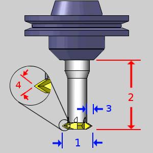
Chamfer Tool
The following items are displayed for informational purposes:
|
|
Machining Data
The Machining Data parameters change slightly depending on whether you are in a Turning job or Mill Turn job. All parameters are explained next.
-
Tool Number - opens the Assigned Tools dialog box for you to change the tool numbering.
-
Override Offsets
![]() Clear the Override Offsets check box to use the tool number to set the
Offset Register value.
Clear the Override Offsets check box to use the tool number to set the
Offset Register value.
![]() Select the Override Offsets check box to allow for manual editing of the
Offset Register value.
Select the Override Offsets check box to allow for manual editing of the
Offset Register value.
- Height Offset - sets
the Height Offset to be used in the posted program.
- Diameter Offset - sets the Diameter Offset to used in the posted program.
Spindle Direction
-
CW - sets the spindle direction to clockwise.
-
CCW - sets the spindle direction to counterclockwise
- Coolant - sets the coolant on code(s) which will be output for the operation. (See the note at the top of the topic for more information on the coolant options)
Feeds and Speeds
By default, the software automatically calculates feeds and speeds based on the values defined in the Stock Material Library.
- Use System
Feeds and Speeds
Select this check
box to automatically calculate the feeds and speeds. Clear this check
box to type feeds and speeds values in the dialog box. - SFM/SMM - is the surface feet/meters per minute feedrate.
- Plunge Feed per Tooth - sets the rate of depth per tooth. The value is linked to the Plunge Feedrate.
- Spindle RPM - is the revolutions per minute of the spindle.
- Plunge Feedrate - is the downward feedrate. This value is linked to the Plunge Feed per Tooth.
- Dwell - sets the amount of seconds to Dwell.
Note: While editing the feeds and speeds, changing one value automatically calculates any other associated values. For example, if you modify the SFM value, the Spindle RPM, Cutting Feedrate, and Plunge Feedrate are automatically calculated.
Counterbore
The following items are displayed for informational purposes:
|
|
Machining Data
The Machining Data parameters change slightly depending on whether you are in a Turning job or Mill Turn job. All parameters are explained next.
-
Tool Number - opens the Assigned Tools dialog box for you to change the tool numbering.
-
Override Offsets
![]() Clear the Override Offsets check box to use the tool number to set the
Offset Register value.
Clear the Override Offsets check box to use the tool number to set the
Offset Register value.
![]() Select the Override Offsets check box to allow for manual editing of the
Offset Register value.
Select the Override Offsets check box to allow for manual editing of the
Offset Register value.
- Height Offset - sets
the Height Offset to be used in the posted program.
- Diameter Offset - sets the Diameter Offset to used in the posted program.
Spindle Direction
-
CW - sets the spindle direction to clockwise.
-
CCW - sets the spindle direction to counterclockwise
- Coolant - sets the coolant on code(s) which will be output for the operation. (See the note at the top of the topic for more information on the coolant options)
Feeds and Speeds
By default, the software automatically calculates feeds and speeds based on the values defined in the Stock Material Library.
- Use System
Feeds and Speeds
Select this check
box to automatically calculate the feeds and speeds. Clear this check
box to type feeds and speeds values in the dialog box. - SFM/SMM - is the surface feet/meters per minute feedrate.
- Plunge Feed per Tooth - sets the rate of depth per tooth. The value is linked to the Plunge Feedrate.
- Spindle RPM - is the revolutions per minute of the spindle.
- Plunge Feedrate - is the downward feedrate. This value is linked to the Plunge Feed per Tooth.
- Dwell - sets the amount of seconds to Dwell.
Note: While editing the feeds and speeds, changing one value automatically calculates any other associated values. For example, if you modify the SFM value, the Spindle RPM, Cutting Feedrate, and Plunge Feedrate are automatically calculated.
Reamer
The following items are displayed for informational purposes:
|
|
Machining Data
The Machining Data parameters change slightly depending on whether you are in a Turning job or Mill Turn job. All parameters are explained next.
-
Tool Number - opens the Assigned Tools dialog box for you to change the tool numbering.
-
Override Offsets
![]() Clear the Override Offsets check box to use the tool number to set the
Offset Register value.
Clear the Override Offsets check box to use the tool number to set the
Offset Register value.
![]() Select the Override Offsets check box to allow for manual editing of the
Offset Register value.
Select the Override Offsets check box to allow for manual editing of the
Offset Register value.
- Height Offset - sets
the Height Offset to be used in the posted program.
- Diameter Offset - sets the Diameter Offset to used in the posted program.
Spindle Direction
-
CW - sets the spindle direction to clockwise.
-
CCW - sets the spindle direction to counterclockwise
- Coolant - sets the coolant on code(s) which will be output for the operation. (See the note at the top of the topic for more information on the coolant options)
Feeds and Speeds
By default, the software automatically calculates feeds and speeds based on the values defined in the Stock Material Library.
- Use System
Feeds and Speeds
Select this check
box to automatically calculate the feeds and speeds. Clear this check
box to type feeds and speeds values in the dialog box. - SFM/SMM - is the surface feet/meters per minute feedrate.
- Plunge Feed per Tooth - sets the rate of depth per tooth. The value is linked to the Plunge Feedrate.
- Spindle RPM - is the revolutions per minute of the spindle.
- Plunge Feedrate - is the downward feedrate. This value is linked to the Plunge Feed per Tooth.
- Dwell - sets the amount of seconds to Dwell.
Note: While editing the feeds and speeds, changing one value automatically calculates any other associated values. For example, if you modify the SFM value, the Spindle RPM, Cutting Feedrate, and Plunge Feedrate are automatically calculated.
Boring
The following items are displayed for informational purposes:
|
|
Machining Data
The Machining Data parameters change slightly depending on whether you are in a Turning job or Mill Turn job. All parameters are explained next.
-
Tool Number - opens the Assigned Tools dialog box for you to change the tool numbering.
-
Override Offsets
![]() Clear the Override Offsets check box to use the tool number to set the
Offset Register value.
Clear the Override Offsets check box to use the tool number to set the
Offset Register value.
![]() Select the Override Offsets check box to allow for manual editing of the
Offset Register value.
Select the Override Offsets check box to allow for manual editing of the
Offset Register value.
- Height Offset - sets
the Height Offset to be used in the posted program.
- Diameter Offset - sets the Diameter Offset to used in the posted program.
Spindle Direction
-
CW - sets the spindle direction to clockwise.
-
CCW - sets the spindle direction to counterclockwise
- Coolant - sets the coolant on code(s) which will be output for the operation. (See the note at the top of the topic for more information on the coolant options)
Feeds and Speeds
By default, the software automatically calculates feeds and speeds based on the values defined in the Stock Material Library.
- Use System
Feeds and Speeds
Select this check
box to automatically calculate the feeds and speeds. Clear this check
box to type feeds and speeds values in the dialog box. - SFM/SMM - is the surface feet/meters per minute feedrate.
- Plunge Feed per Tooth - sets the rate of depth per tooth. The value is linked to the Plunge Feedrate.
- Spindle RPM - is the revolutions per minute of the spindle.
- Plunge Feedrate - is the downward feedrate. This value is linked to the Plunge Feed per Tooth.
- Dwell - sets the amount of seconds to Dwell.
Note: While editing the feeds and speeds, changing one value automatically calculates any other associated values. For example, if you modify the SFM value, the Spindle RPM, Cutting Feedrate, and Plunge Feedrate are automatically calculated.
Mill
Endmill Rough
The following items are displayed for informational purposes:
|
|
Machining Data
The Machining Data parameters change slightly depending on whether you are in a Turning job or Mill Turn job. All parameters are explained next.
-
Tool Number - opens the Assigned Tools dialog box for you to change the tool numbering.
-
Override Offsets
![]() Clear the Override Offsets check box to use the tool number to set the
Offset Register value.
Clear the Override Offsets check box to use the tool number to set the
Offset Register value.
![]() Select the Override Offsets check box to allow for manual editing of the
Offset Register value.
Select the Override Offsets check box to allow for manual editing of the
Offset Register value.
- Height Offset - sets
the Height Offset to be used in the posted program.
- Diameter Offset - sets the Diameter Offset to used in the posted program.
Spindle Direction
-
CW - sets the spindle direction to clockwise.
-
CCW - sets the spindle direction to counterclockwise
- Coolant - sets the coolant on code(s) which will be output for the operation. (See the note at the top of the topic for more information on the coolant options)
Feeds and Speeds
By default, the software automatically calculates feeds and speeds based on the values defined in the Stock Material Library.
- Use System Feeds and Speeds
![]() Select this check
box to automatically calculate the feeds and speeds.
Select this check
box to automatically calculate the feeds and speeds.
![]() Clear this check
box to type feeds and speeds values in the dialog box.
Clear this check
box to type feeds and speeds values in the dialog box.
- SFM/SMM - is the surface feet/meters per minute feedrate.
- Feed per Tooth - is the feedrate for feed moves in units per tooth.
- Plunge Feed per Tooth - is the feedrate for plunge moves in units per tooth.
- Spindle RPM - is the revolutions per minute of the spindle.
- Cutting Feedrate - is the feedrate for feed moves.
- Plunge Feedrate - is the feedrate for plunge moves.
- Arc Slowdown % - is the amount of the feedrate to use when in arc moves. 100% is equal to the Cutting Feedrate.
Note: While editing the feeds and speeds, changing one value automatically calculates any other associated values. For example, if you modify the SFM value, the Spindle RPM, Cutting Feedrate, and Plunge Feedrate are automatically calculated.
Endmill Finish
The following items are displayed for informational purposes:
|
|
Machining Data
The Machining Data parameters change slightly depending on whether you are in a Turning job or Mill Turn job. All parameters are explained next.
-
Tool Number - opens the Assigned Tools dialog box for you to change the tool numbering.
-
Override Offsets
![]() Clear the Override Offsets check box to use the tool number to set the
Offset Register value.
Clear the Override Offsets check box to use the tool number to set the
Offset Register value.
![]() Select the Override Offsets check box to allow for manual editing of the
Offset Register value.
Select the Override Offsets check box to allow for manual editing of the
Offset Register value.
- Height Offset - sets
the Height Offset to be used in the posted program.
- Diameter Offset - sets the Diameter Offset to used in the posted program.
Spindle Direction
-
CW - sets the spindle direction to clockwise.
-
CCW - sets the spindle direction to counterclockwise
- Coolant - sets the coolant on code(s) which will be output for the operation. (See the note at the top of the topic for more information on the coolant options)
Feeds and Speeds
By default, the software automatically calculates feeds and speeds based on the values defined in the Stock Material Library.
- Use System Feeds and Speeds
![]() Select this check
box to automatically calculate the feeds and speeds.
Select this check
box to automatically calculate the feeds and speeds.
![]() Clear this check
box to type feeds and speeds values in the dialog box.
Clear this check
box to type feeds and speeds values in the dialog box.
- SFM/SMM - is the surface feet/meters per minute feedrate.
- Feed per Tooth - is the feedrate for feed moves in units per tooth.
- Plunge Feed per Tooth - is the feedrate for plunge moves in units per tooth.
- Spindle RPM - is the revolutions per minute of the spindle.
- Cutting Feedrate - is the feedrate for feed moves.
- Plunge Feedrate - is the feedrate for plunge moves.
- Arc Slowdown % - is the amount of the feedrate to use when in arc moves. 100% is equal to the Cutting Feedrate.
Note: While editing the feeds and speeds, changing one value automatically calculates any other associated values. For example, if you modify the SFM value, the Spindle RPM, Cutting Feedrate, and Plunge Feedrate are automatically calculated.
Chamfer Mill
The following items are displayed for informational purposes:
|
|
Machining Data
The Machining Data parameters change slightly depending on whether you are in a Turning job or Mill Turn job. All parameters are explained next.
-
Tool Number - opens the Assigned Tools dialog box for you to change the tool numbering.
-
Override Offsets
![]() Clear the Override Offsets check box to use the tool number to set the
Offset Register value.
Clear the Override Offsets check box to use the tool number to set the
Offset Register value.
![]() Select the Override Offsets check box to allow for manual editing of the
Offset Register value.
Select the Override Offsets check box to allow for manual editing of the
Offset Register value.
- Height Offset - sets
the Height Offset to be used in the posted program.
- Diameter Offset - sets the Diameter Offset to used in the posted program.
Spindle Direction
-
CW - sets the spindle direction to clockwise.
-
CCW - sets the spindle direction to counterclockwise
- Coolant - sets the coolant on code(s) which will be output for the operation. (See the note at the top of the topic for more information on the coolant options)
Feeds and Speeds
By default, the software automatically calculates feeds and speeds based on the values defined in the Stock Material Library.
- Use System Feeds and Speeds
![]() Select this check
box to automatically calculate the feeds and speeds.
Select this check
box to automatically calculate the feeds and speeds.
![]() Clear this check
box to type feeds and speeds values in the dialog box.
Clear this check
box to type feeds and speeds values in the dialog box.
- SFM/SMM - is the surface feet/meters per minute feedrate.
- Feed per Tooth - is the feedrate for feed moves in units per tooth.
- Plunge Feed per Tooth - is the feedrate for plunge moves in units per tooth.
- Spindle RPM - is the revolutions per minute of the spindle.
- Cutting Feedrate - is the feedrate for feed moves.
- Plunge Feedrate - is the feedrate for plunge moves.
- Arc Slowdown % - is the amount of the feedrate to use when in arc moves. 100% is equal to the Cutting Feedrate.
Note: While editing the feeds and speeds, changing one value automatically calculates any other associated values. For example, if you modify the SFM value, the Spindle RPM, Cutting Feedrate, and Plunge Feedrate are automatically calculated.
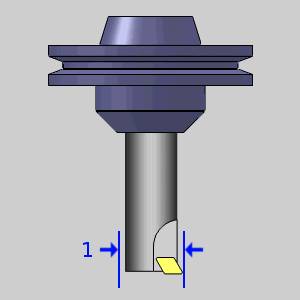
Corner-Round
When defining a corner rounding tool, the diameter must be greater than or equal to the small diameter plus twice the corner radius.
Diameter >= Small Diameter + (Corner Radius * 2)
If you enter values that do not fit this equation, an error message displays.
Tip: When defining a corner rounding tool, if the Diameter is greater than the current/default value, set the Diameter value first. This allows you to avoid receiving the error message. If the Diameter is less than the current/default value, set the Corner Radius first to avoid the error message.
The following items are displayed for informational purposes:
|
|
Machining Data
The Machining Data parameters change slightly depending on whether you are in a Turning job or Mill Turn job. All parameters are explained next.
-
Tool Number - opens the Assigned Tools dialog box for you to change the tool numbering.
-
Override Offsets
![]() Clear the Override Offsets check box to use the tool number to set the
Offset Register value.
Clear the Override Offsets check box to use the tool number to set the
Offset Register value.
![]() Select the Override Offsets check box to allow for manual editing of the
Offset Register value.
Select the Override Offsets check box to allow for manual editing of the
Offset Register value.
- Height Offset - sets
the Height Offset to be used in the posted program.
- Diameter Offset - sets the Diameter Offset to used in the posted program.
Spindle Direction
-
CW - sets the spindle direction to clockwise.
-
CCW - sets the spindle direction to counterclockwise
- Coolant - sets the coolant on code(s) which will be output for the operation. (See the note at the top of the topic for more information on the coolant options)
Feeds and Speeds
By default, the software automatically calculates feeds and speeds based on the values defined in the Stock Material Library.
- Use System Feeds and Speeds
![]() Select this check
box to automatically calculate the feeds and speeds.
Select this check
box to automatically calculate the feeds and speeds.
![]() Clear this check
box to type feeds and speeds values in the dialog box.
Clear this check
box to type feeds and speeds values in the dialog box.
- SFM/SMM - is the surface feet/meters per minute feedrate.
- Feed per Tooth - is the feedrate for feed moves in units per tooth.
- Plunge Feed per Tooth - is the feedrate for plunge moves in units per tooth.
- Spindle RPM - is the revolutions per minute of the spindle.
- Cutting Feedrate - is the feedrate for feed moves.
- Plunge Feedrate - is the feedrate for plunge moves.
- Arc Slowdown % - is the amount of the feedrate to use when in arc moves. 100% is equal to the Cutting Feedrate.
Note: While editing the feeds and speeds, changing one value automatically calculates any other associated values. For example, if you modify the SFM value, the Spindle RPM, Cutting Feedrate, and Plunge Feedrate are automatically calculated.
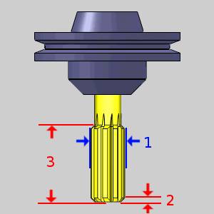
Thread Mill
The following items are displayed for informational purposes:
|
|
Machining Data
The Machining Data parameters change slightly depending on whether you are in a Turning job or Mill Turn job. All parameters are explained next.
-
Tool Number - opens the Assigned Tools dialog box for you to change the tool numbering.
-
Override Offsets
![]() Clear the Override Offsets check box to use the tool number to set the
Offset Register value.
Clear the Override Offsets check box to use the tool number to set the
Offset Register value.
![]() Select the Override Offsets check box to allow for manual editing of the
Offset Register value.
Select the Override Offsets check box to allow for manual editing of the
Offset Register value.
- Height Offset - sets
the Height Offset to be used in the posted program.
- Diameter Offset - sets the Diameter Offset to used in the posted program.
Spindle Direction
-
CW - sets the spindle direction to clockwise.
-
CCW - sets the spindle direction to counterclockwise
- Coolant - sets the coolant on code(s) which will be output for the operation. (See the note at the top of the topic for more information on the coolant options)
Feeds and Speeds
By default, the software automatically calculates feeds and speeds based on the values defined in the Stock Material Library.
- Use System Feeds and Speeds
![]() Select this check
box to automatically calculate the feeds and speeds.
Select this check
box to automatically calculate the feeds and speeds.
![]() Clear this check
box to type feeds and speeds values in the dialog box.
Clear this check
box to type feeds and speeds values in the dialog box.
- SFM/SMM - is the surface feet/meters per minute feedrate.
- Feed per Tooth - is the feedrate for feed moves in units per tooth.
- Plunge Feed per Tooth - is the feedrate for plunge moves in units per tooth.
- Spindle RPM - is the revolutions per minute of the spindle.
- Cutting Feedrate - is the feedrate for feed moves.
- Plunge Feedrate - is the feedrate for plunge moves.
- Arc Slowdown % - is the amount of the feedrate to use when in arc moves. 100% is equal to the Cutting Feedrate.
Note: While editing the feeds and speeds, changing one value automatically calculates any other associated values. For example, if you modify the SFM value, the Spindle RPM, Cutting Feedrate, and Plunge Feedrate are automatically calculated.
Single Point Thread
The following items are displayed for informational purposes:
|
|
Machining Data
The Machining Data parameters change slightly depending on whether you are in a Turning job or Mill Turn job. All parameters are explained next.
-
Tool Number - opens the Assigned Tools dialog box for you to change the tool numbering.
-
Override Offsets
![]() Clear the Override Offsets check box to use the tool number to set the
Offset Register value.
Clear the Override Offsets check box to use the tool number to set the
Offset Register value.
![]() Select the Override Offsets check box to allow for manual editing of the
Offset Register value.
Select the Override Offsets check box to allow for manual editing of the
Offset Register value.
- Height Offset - sets
the Height Offset to be used in the posted program.
- Diameter Offset - sets the Diameter Offset to used in the posted program.
Spindle Direction
-
CW - sets the spindle direction to clockwise.
-
CCW - sets the spindle direction to counterclockwise
- Coolant - sets the coolant on code(s) which will be output for the operation. (See the note at the top of the topic for more information on the coolant options)
Feeds and Speeds
By default, the software automatically calculates feeds and speeds based on the values defined in the Stock Material Library.
- Use System Feeds and Speeds
![]() Select this check
box to automatically calculate the feeds and speeds.
Select this check
box to automatically calculate the feeds and speeds.
![]() Clear this check
box to type feeds and speeds values in the dialog box.
Clear this check
box to type feeds and speeds values in the dialog box.
- SFM/SMM - is the surface feet/meters per minute feedrate.
- Feed per Tooth - is the feedrate for feed moves in units per tooth.
- Plunge Feed per Tooth - is the feedrate for plunge moves in units per tooth.
- Spindle RPM - is the revolutions per minute of the spindle.
- Cutting Feedrate - is the feedrate for feed moves.
- Plunge Feedrate - is the feedrate for plunge moves.
- Arc Slowdown % - is the amount of the feedrate to use when in arc moves. 100% is equal to the Cutting Feedrate.
Note: While editing the feeds and speeds, changing one value automatically calculates any other associated values. For example, if you modify the SFM value, the Spindle RPM, Cutting Feedrate, and Plunge Feedrate are automatically calculated.
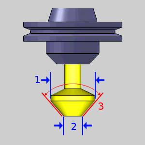
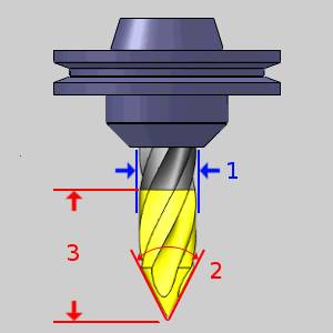
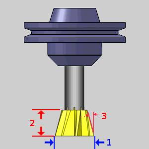
V-Tool
The following items are displayed for informational purposes:
|
|
Machining Data
The Machining Data parameters change slightly depending on whether you are in a Turning job or Mill Turn job. All parameters are explained next.
-
Tool Number - opens the Assigned Tools dialog box for you to change the tool numbering.
-
Override Offsets
![]() Clear the Override Offsets check box to use the tool number to set the
Offset Register value.
Clear the Override Offsets check box to use the tool number to set the
Offset Register value.
![]() Select the Override Offsets check box to allow for manual editing of the
Offset Register value.
Select the Override Offsets check box to allow for manual editing of the
Offset Register value.
- Height Offset - sets
the Height Offset to be used in the posted program.
- Diameter Offset - sets the Diameter Offset to used in the posted program.
Spindle Direction
-
CW - sets the spindle direction to clockwise.
-
CCW - sets the spindle direction to counterclockwise
- Coolant - sets the coolant on code(s) which will be output for the operation. (See the note at the top of the topic for more information on the coolant options)
Feeds and Speeds
By default, the software automatically calculates feeds and speeds based on the values defined in the Stock Material Library.
- Use System Feeds and Speeds
![]() Select this check
box to automatically calculate the feeds and speeds.
Select this check
box to automatically calculate the feeds and speeds.
![]() Clear this check
box to type feeds and speeds values in the dialog box.
Clear this check
box to type feeds and speeds values in the dialog box.
- SFM/SMM - is the surface feet/meters per minute feedrate.
- Feed per Tooth - is the feedrate for feed moves in units per tooth.
- Plunge Feed per Tooth - is the feedrate for plunge moves in units per tooth.
- Spindle RPM - is the revolutions per minute of the spindle.
- Cutting Feedrate - is the feedrate for feed moves.
- Plunge Feedrate - is the feedrate for plunge moves.
- Arc Slowdown % - is the amount of the feedrate to use when in arc moves. 100% is equal to the Cutting Feedrate.
Note: While editing the feeds and speeds, changing one value automatically calculates any other associated values. For example, if you modify the SFM value, the Spindle RPM, Cutting Feedrate, and Plunge Feedrate are automatically calculated.
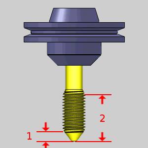
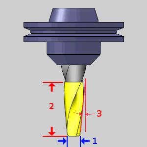
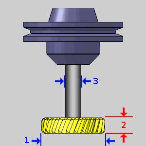
Tapered
The following items are displayed for informational purposes:
|
|
Machining Data
The Machining Data parameters change slightly depending on whether you are in a Turning job or Mill Turn job. All parameters are explained next.
-
Tool Number - opens the Assigned Tools dialog box for you to change the tool numbering.
-
Override Offsets
![]() Clear the Override Offsets check box to use the tool number to set the
Offset Register value.
Clear the Override Offsets check box to use the tool number to set the
Offset Register value.
![]() Select the Override Offsets check box to allow for manual editing of the
Offset Register value.
Select the Override Offsets check box to allow for manual editing of the
Offset Register value.
- Height Offset - sets
the Height Offset to be used in the posted program.
- Diameter Offset - sets the Diameter Offset to used in the posted program.
Spindle Direction
-
CW - sets the spindle direction to clockwise.
-
CCW - sets the spindle direction to counterclockwise
- Coolant - sets the coolant on code(s) which will be output for the operation. (See the note at the top of the topic for more information on the coolant options)
Feeds and Speeds
By default, the software automatically calculates feeds and speeds based on the values defined in the Stock Material Library.
- Use System Feeds and Speeds
![]() Select this check
box to automatically calculate the feeds and speeds.
Select this check
box to automatically calculate the feeds and speeds.
![]() Clear this check
box to type feeds and speeds values in the dialog box.
Clear this check
box to type feeds and speeds values in the dialog box.
- SFM/SMM - is the surface feet/meters per minute feedrate.
- Feed per Tooth - is the feedrate for feed moves in units per tooth.
- Plunge Feed per Tooth - is the feedrate for plunge moves in units per tooth.
- Spindle RPM - is the revolutions per minute of the spindle.
- Cutting Feedrate - is the feedrate for feed moves.
- Plunge Feedrate - is the feedrate for plunge moves.
- Arc Slowdown % - is the amount of the feedrate to use when in arc moves. 100% is equal to the Cutting Feedrate.
Note: While editing the feeds and speeds, changing one value automatically calculates any other associated values. For example, if you modify the SFM value, the Spindle RPM, Cutting Feedrate, and Plunge Feedrate are automatically calculated.
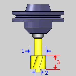
T-Cutter
The following items are displayed for informational purposes:
|
|
Machining Data
The Machining Data parameters change slightly depending on whether you are in a Turning job or Mill Turn job. All parameters are explained next.
-
Tool Number - opens the Assigned Tools dialog box for you to change the tool numbering.
-
Override Offsets
![]() Clear the Override Offsets check box to use the tool number to set the
Offset Register value.
Clear the Override Offsets check box to use the tool number to set the
Offset Register value.
![]() Select the Override Offsets check box to allow for manual editing of the
Offset Register value.
Select the Override Offsets check box to allow for manual editing of the
Offset Register value.
- Height Offset - sets
the Height Offset to be used in the posted program.
- Diameter Offset - sets the Diameter Offset to used in the posted program.
Spindle Direction
-
CW - sets the spindle direction to clockwise.
-
CCW - sets the spindle direction to counterclockwise
- Coolant - sets the coolant on code(s) which will be output for the operation. (See the note at the top of the topic for more information on the coolant options)
Feeds and Speeds
By default, the software automatically calculates feeds and speeds based on the values defined in the Stock Material Library.
- Use System Feeds and Speeds
![]() Select this check
box to automatically calculate the feeds and speeds.
Select this check
box to automatically calculate the feeds and speeds.
![]() Clear this check
box to type feeds and speeds values in the dialog box.
Clear this check
box to type feeds and speeds values in the dialog box.
- SFM/SMM - is the surface feet/meters per minute feedrate.
- Feed per Tooth - is the feedrate for feed moves in units per tooth.
- Plunge Feed per Tooth - is the feedrate for plunge moves in units per tooth.
- Spindle RPM - is the revolutions per minute of the spindle.
- Cutting Feedrate - is the feedrate for feed moves.
- Plunge Feedrate - is the feedrate for plunge moves.
- Arc Slowdown % - is the amount of the feedrate to use when in arc moves. 100% is equal to the Cutting Feedrate.
Note: While editing the feeds and speeds, changing one value automatically calculates any other associated values. For example, if you modify the SFM value, the Spindle RPM, Cutting Feedrate, and Plunge Feedrate are automatically calculated.
Dove Mill
The following items are displayed for informational purposes:
|
|
Machining Data
The Machining Data parameters change slightly depending on whether you are in a Turning job or Mill Turn job. All parameters are explained next.
-
Tool Number - opens the Assigned Tools dialog box for you to change the tool numbering.
-
Override Offsets
![]() Clear the Override Offsets check box to use the tool number to set the
Offset Register value.
Clear the Override Offsets check box to use the tool number to set the
Offset Register value.
![]() Select the Override Offsets check box to allow for manual editing of the
Offset Register value.
Select the Override Offsets check box to allow for manual editing of the
Offset Register value.
- Height Offset - sets
the Height Offset to be used in the posted program.
- Diameter Offset - sets the Diameter Offset to used in the posted program.
Spindle Direction
-
CW - sets the spindle direction to clockwise.
-
CCW - sets the spindle direction to counterclockwise
- Coolant - sets the coolant on code(s) which will be output for the operation. (See the note at the top of the topic for more information on the coolant options)
Feeds and Speeds
By default, the software automatically calculates feeds and speeds based on the values defined in the Stock Material Library.
- Use System Feeds and Speeds
![]() Select this check
box to automatically calculate the feeds and speeds.
Select this check
box to automatically calculate the feeds and speeds.
![]() Clear this check
box to type feeds and speeds values in the dialog box.
Clear this check
box to type feeds and speeds values in the dialog box.
- SFM/SMM - is the surface feet/meters per minute feedrate.
- Feed per Tooth - is the feedrate for feed moves in units per tooth.
- Plunge Feed per Tooth - is the feedrate for plunge moves in units per tooth.
- Spindle RPM - is the revolutions per minute of the spindle.
- Cutting Feedrate - is the feedrate for feed moves.
- Plunge Feedrate - is the feedrate for plunge moves.
- Arc Slowdown % - is the amount of the feedrate to use when in arc moves. 100% is equal to the Cutting Feedrate.
Note: While editing the feeds and speeds, changing one value automatically calculates any other associated values. For example, if you modify the SFM value, the Spindle RPM, Cutting Feedrate, and Plunge Feedrate are automatically calculated.
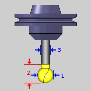
Lollipop
The following items are displayed for informational purposes:
|
|
Machining Data
The Machining Data parameters change slightly depending on whether you are in a Turning job or Mill Turn job. All parameters are explained next.
-
Tool Number - opens the Assigned Tools dialog box for you to change the tool numbering.
-
Override Offsets
![]() Clear the Override Offsets check box to use the tool number to set the
Offset Register value.
Clear the Override Offsets check box to use the tool number to set the
Offset Register value.
![]() Select the Override Offsets check box to allow for manual editing of the
Offset Register value.
Select the Override Offsets check box to allow for manual editing of the
Offset Register value.
- Height Offset - sets
the Height Offset to be used in the posted program.
- Diameter Offset - sets the Diameter Offset to used in the posted program.
Spindle Direction
-
CW - sets the spindle direction to clockwise.
-
CCW - sets the spindle direction to counterclockwise
- Coolant - sets the coolant on code(s) which will be output for the operation. (See the note at the top of the topic for more information on the coolant options)
Feeds and Speeds
By default, the software automatically calculates feeds and speeds based on the values defined in the Stock Material Library.
- Use System Feeds and Speeds
![]() Select this check
box to automatically calculate the feeds and speeds.
Select this check
box to automatically calculate the feeds and speeds.
![]() Clear this check
box to type feeds and speeds values in the dialog box.
Clear this check
box to type feeds and speeds values in the dialog box.
- SFM/SMM - is the surface feet/meters per minute feedrate.
- Feed per Tooth - is the feedrate for feed moves in units per tooth.
- Plunge Feed per Tooth - is the feedrate for plunge moves in units per tooth.
- Spindle RPM - is the revolutions per minute of the spindle.
- Cutting Feedrate - is the feedrate for feed moves.
- Plunge Feedrate - is the feedrate for plunge moves.
- Arc Slowdown % - is the amount of the feedrate to use when in arc moves. 100% is equal to the Cutting Feedrate.
Note: While editing the feeds and speeds, changing one value automatically calculates any other associated values. For example, if you modify the SFM value, the Spindle RPM, Cutting Feedrate, and Plunge Feedrate are automatically calculated.
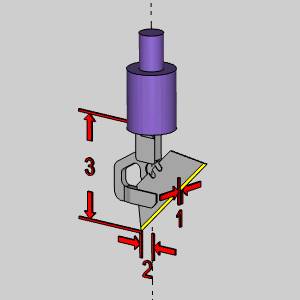
Drag Knife
The following items are displayed for informational purposes:
|
|
Machining Data
The Machining Data parameters change slightly depending on whether you are in a Turning job or Mill Turn job. All parameters are explained next.
-
Tool Number - opens the Assigned Tools dialog box for you to change the tool numbering.
-
Override Offsets
![]() Clear the Override Offsets check box to use the tool number to set the
Offset Register value.
Clear the Override Offsets check box to use the tool number to set the
Offset Register value.
![]() Select the Override Offsets check box to allow for manual editing of the
Offset Register value.
Select the Override Offsets check box to allow for manual editing of the
Offset Register value.
- Height Offset - sets
the Height Offset to be used in the posted program.
- Diameter Offset - sets the Diameter Offset to used in the posted program.
Spindle Direction
-
CW - sets the spindle direction to clockwise.
-
CCW - sets the spindle direction to counterclockwise
- Coolant - sets the coolant on code(s) which will be output for the operation. (See the note at the top of the topic for more information on the coolant options)
Feeds and Speeds
- Cutting Feedrate - is the feedrate for feed moves.
- Plunge Feedrate - is the feedrate for plunge moves.
- Arc Slowdown % - is the amount of the feedrate to use when in arc moves. 100% is equal to the Cutting Feedrate.
Turning
Lathe Rough / Finish / Boring
|
|
|
|
|
|
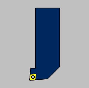
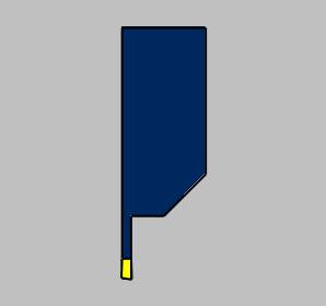
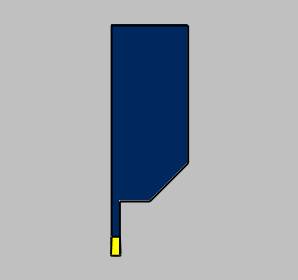
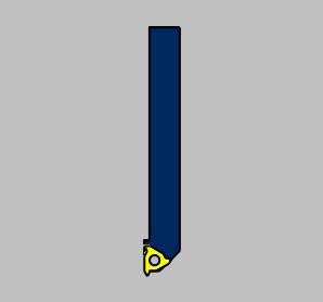
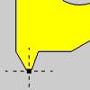
 Rough Tool
![]() Finish Tool
Finish Tool ![]() Boring Tool
Boring Tool
Tool Data
|
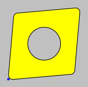
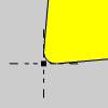
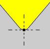
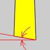
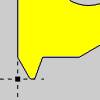
Reference Point - allows you to choose an alignment of the reference point to the insert. |
||||||
|
| Shape - sets the shape designation of the insert. | Clearance - sets the clearance designation of the insert. | |||||||||||||||||||||||||||||||||||||||||||||||||||||||||||||||||||||||
|
|


- Tolerance - sets
the tolerance designation of the insert. This does not affect
toolpath or output.
- Type - sets the
type designation of the insert. This does not affect toolpath
or output.
- Nose Radius - sets
the radius of the tool nose.
- IC Diameter - sets the internal circumference
of the insert.
- Tool Label - adds a name to the tool, in the tool list, that allows you to easily identify the tool.
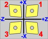
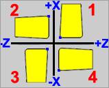
Tool Orientation
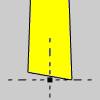
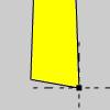
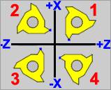
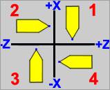
- Insert Orientation - 1-4 sets the orientation of the tool as shown in the image. This selection influences the ability of the tool to move into locations that are restricted by adjacent geometry. The options available depend on the operation type.
Note: NOTE: The Orientation Number defines whether the cut is inside or outside of the geometry and the direction of cut and will be set for you based on the Feature Type and Region chosen in the Feature page.
-
Vertical - sets
the holder to a vertical orientation.
-
Horizontal - sets
the holder to a horizontal orientation.
- Custom Angle
- The default tool angle will be used. - Selecting this check box allows you to set a particular
angle to the holder.
Machining Data
The Machining Data parameters change slightly depending on whether you are in a Turning job or Mill Turn job. All parameters are explained next.
- Tool Number - opens the Assigned
Tools dialog box for you to change the tool numbering.
- For
Mill Turn jobs, view the Assigned
Tools for Mill Turn.
- Override Offsets
Clear the Override Offsets check box to use the tool number to set the
Offset Register value.
Select the Override Offsets check box to allow for manual editing of the
Offset Register value.
- Offset Register 1 (Diameter) - sets the register on the machine that stores the diameter offset
values for the tool.
- Offset Register 2 (Height) - sets the register
on the machine that stores the height offset values for the tool (Mill
Turn jobs only).
- Suffix Code - is an alphanumeric value used for the tool numbering for certain mill-turn machines, generally those with Mazak controllers (Mill Turn jobs only).
Spindle Direction
- CW - outputs the command for clockwise rotation of the spindle.
- CCW - outputs the command for counter-clockwise rotation of the spindle.
- Tool Angle Control - opens the Tool Angle Control dialog box for you to specify the rotation angles for both the milling head and lathe tool for the operation. This is used only for operations performed with a milling spindle/head and turning tool mounted to it (Mill Turn only).
- Coolant - sets the coolant option for the operation. Select one of the following options: Off, Flood, Mist, Air, or Oil.
Feeds and Speeds
-
RPM
- sets the feeds and speeds to revolutions per minute.
-
CSS
- sets the feeds and speeds to a constant surface speed.
- Maximum
RPM - sets the limits of the spindle speed in the posted
NC program.
- Spindle
RPM/SFM - sets the spindle speed for the feature in revolutions
per minute or the surface feet per minute based on the selected
RPM/CSS option.
- Feedrate - sets the feedrate for the feature.
Lathe Groove / Cutoff
| Groove Tool | Cutoff Tool | ||
|
|
|
|
|
|
|
|

|
|

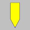
![]() Groove Tool
Groove Tool ![]() Cutoff Tool
Cutoff Tool
Tool Data
|
Reference Point - allows you to choose an alignment of the reference point to the insert. |
||||||||||||||||||
|
||||||||||||||||||
- Corner Radius - sets the size of the inserts corner radius.
- Tool Width - sets the width of the insert.
- Tool Height - sets the height of the insert.
- Side Angle -
sets the side angle of the insert.
| Groove Tool | Cutoff Tool |
|
|
|
- Tip Angle -
sets the bottom angle of the insert for the cutoff tool.
| Cutoff Tool Only |
|
|
- Tool Label - adds a name to the tool, in the tool list, that allows you to easily identify the tool.
Tool Orientation
This section is unavailable for the Lathe Cutoff tool.
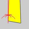
- Insert Orientation - 1-4 sets the orientation of the tool as shown in the image. This selection influences the ability of the tool to move into locations that are restricted by adjacent geometry. The options available depend on the operation type.
Note: NOTE: The Orientation Number defines whether the cut is inside or outside of the geometry and the direction of cut and will be set for you based on the Feature Type and Region chosen in the Feature page.
- Custom Angle
- The default tool angle will be used. - Selecting this check box allows you to set a particular
angle to the holder.
Machining Data
The Machining Data parameters change slightly depending on whether you are in a Turning job or Mill Turn job. All parameters are explained next.
- Tool Number - opens the Assigned
Tools dialog box for you to change the tool numbering.
- For
Mill Turn jobs, view the Assigned
Tools for Mill Turn.
- Override Offsets
Clear the Override Offsets check box to use the tool number to set the
Offset Register value.
Select the Override Offsets check box to allow for manual editing of the
Offset Register value.
- Offset Register 1 (Diameter) - sets the register on the machine that stores the diameter offset
values for the tool.
- Offset Register 2 (Height) - sets the register
on the machine that stores the height offset values for the tool (Mill
Turn jobs only).
- Suffix Code - is an alphanumeric value used for the tool numbering for certain mill-turn machines, generally those with Mazak controllers (Mill Turn jobs only).
Spindle Direction
- CW - outputs the command for clockwise rotation of the spindle.
- CCW - outputs the command for counter-clockwise rotation of the spindle.
- Tool Angle Control - opens the Tool Angle Control dialog box for you to specify the rotation angles for both the milling head and lathe tool for the operation. This is used only for operations performed with a milling spindle/head and turning tool mounted to it (Mill Turn only).
- Coolant - sets the coolant option for the operation. Select one of the following options: Off, Flood, Mist, Air, or Oil.
Feeds and Speeds
-
RPM
- sets the feeds and speeds to revolutions per minute.
-
CSS
- sets the feeds and speeds to a constant surface speed.
- Maximum
RPM - sets the limits of the spindle speed in the posted
NC program.
- Spindle
RPM/SFM - sets the spindle speed for the feature in revolutions
per minute or the surface feet per minute based on the selected
RPM/CSS option.
- Feedrate - sets the feedrate for the feature.
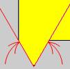
Lathe Thread
|
|
||||||||||||||||||||||||||||


Machining Data
The Machining Data parameters change slightly depending on whether you are in a Turning job or Mill Turn job. All parameters are explained next.
- Tool Number - opens the Assigned
Tools dialog box for you to change the tool numbering.
- For
Mill Turn jobs, view the Assigned
Tools for Mill Turn.
- Override Offsets
Clear the Override Offsets check box to use the tool number to set the
Offset Register value.
Select the Override Offsets check box to allow for manual editing of the
Offset Register value.
- Offset Register 1 (Diameter) - sets the register on the machine that stores the diameter offset
values for the tool.
- Offset Register 2 (Height) - sets the register
on the machine that stores the height offset values for the tool (Mill
Turn jobs only).
- Suffix Code - is an alphanumeric value used for the tool numbering for certain mill-turn machines, generally those with Mazak controllers (Mill Turn jobs only).
Spindle Direction
- CW - outputs the command for clockwise rotation of the spindle.
- CCW - outputs the command for counter-clockwise rotation of the spindle.
- Tool Angle Control - opens the Tool Angle Control dialog box for you to specify the rotation angles for both the milling head and lathe tool for the operation. This is used only for operations performed with a milling spindle/head and turning tool mounted to it (Mill Turn only).
- Coolant - sets the coolant option for the operation. Select one of the following options: Off, Flood, Mist, Air, or Oil.
Feeds and Speeds
-
RPM
- sets the feeds and speeds to revolutions per minute.
- Maximum
RPM - sets the limits of the spindle speed in the posted
NC program.
- Spindle
RPM/SFM - sets the spindle speed for the feature in revolutions
per minute or the surface feet per minute based on the selected
RPM/CSS option.
- Pitch/Feed - is the pitch
of the thread and therefore the distance per revolution.
- Maximum
RPM - sets the limits of the spindle speed in the posted
NC program.
Note: The Pitch/Feed value is controlled by adjusting the Pitch on the Parameters page.
Next Topic
Once the Tool variables have been set, clicking Next>> will take you to the next page of the given operation. To move the appropriate next topic, click the type of feature that has been chosen below and then the link for the desired operation.
Center Drill Parameters
Drill Operation Parameters
Chamfer Drill Parameters
Chamfer Mill Patterns
Ream Parameters
Bore Parameters
Rolling Tap Parameters
Counterbore Drill Parameters
Counterbore Mill Parameters
Tap Parameters
Rolling Tap Parameters
Facing Patterns
Profile Rough Patterns
Profile Finish Patterns
Pocket Patterns
Facing Patterns
Engrave Parameters
Chamfer Mill Patterns
Plunge Rough (2 Axis) Patterns
Corner Rounding Patterns
Z Level Rough Patterns
Z Level Finish Patterns
Planar Patterns
Spiral Patterns
Radial Patterns
Plunge Rough Patterns
Advanced Rough Patterns
Flatlands Parameters
Equidistant Patterns
Pencil Parameters
Advanced Planar Patterns
Project Curves Patterns
Advanced Z Level Finish Patterns
4 Axis Rotary Patterns
Mill Thread Pattern
3 Axis Wireframe Parameters
Thread Parameters
Cutoff Parameters
Stock Handling Parameters